During an interview the other day I was asked to describe how we determine the UAP of a Bluetooth address with Ubertooth. A few minutes after the interview I realized that I oversimplified and got one detail wrong: I mentioned whitening when I should have talked about the HEC and CRC. Considering that only a few people in the world have intimate knowledge of our method, I thought it would be a good idea to describe it more thoroughly and correctly for posterity. It’s complicated, and I don’t think we’ve ever attempted to fully describe it anywhere but in the convoluted source code of libbtbb.
I’m writing about classic Bluetooth, by the way, not Bluetooth Low Energy (LE) also known as Bluetooth Smart. In general, these sorts of things are easier with LE, so they do not require such long-winded explanations.
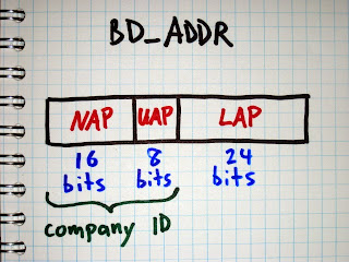
The Upper Address Part (UAP) is a particular 8 bit section of a Bluetooth Device Address (BD_ADDR). In order to fully decode Bluetooth packets, determine a Bluetooth hopping sequence, or do anything else interesting with Bluetooth, we need to know the UAP in addition to the Lower Address Part (LAP) of the piconet’s master device.

The master’s 24 bit LAP is easy to discover using a tool like Ubertooth that can demodulate Bluetooth packets. Every Bluetooth packet includes the master’s LAP as a part of the sync word at the beginning of the packet. It is transmitted in the clear, so we only have to capture and demodulate one packet in order to learn the LAP.
The UAP is harder to determine, but there are multiple methods available to us. The simplest method is brute force search. As Joshua Wright showed in Hacking Exposed Wireless, Second Edition, it is possible to try connecting to a target’s BD_ADDR over and over, guessing a new UAP each time. Because the Non-significant Address Part (NAP) is ignored during the initial connection process, it doesn’t matter what value we use; we only need the correct LAP and UAP. Since the UAP is 8 bits, there are only 256 possible values to try, and a correct match can typically be found quite quickly by prioritizing common UAPs, possible because the UAP is part of the Organizationally Unique Identifier (OUI) assigned to manufacturers (and there is a fairly small number of companies that make the majority of Bluetooth devices). Common UOIs can be identified thanks to the BNAP BNAP project.
Brute force is an excellent method to have in our toolbox, but it has some drawbacks. First, it is an active attack that can influence the behavior of the target devices and that can be detected by a monitoring system. Second, it only works if the master device is in a connectable state. Many devices do not enter the connectable state when they already have an active connection. Annoyingly, many devices are connectable for only brief periods of time (one out of every five seconds, for example), slowing down a brute force search.
The Ubertooth project aims to provide the best possible tools for passive monitoring of Bluetooth systems, so we implement a method of UAP discovery that does not require active transmission.
We think of the problem as being a search for the correct UAP out of a search space that is 8 bits in size (having 256 candidates). We do not have any method to observe the UAP directly, so we instead perform a series of techniques that reduce the search space by a process of elimination until only one possible UAP remains.
Our first technique is to compute the UAP by reversing the Header Error Check (HEC) that appears at the end of the header of every packet that has a header. The HEC is an 8 bit value computed from the master’s UAP and the header bytes. The purpose of the HEC is to allow a receiver to verify that the packet header was received correctly, without any unrecovered bit errors. We assume that we received the packet without bit errors (which is true most of the time). After decoding the HEC and the packet bytes it is possible to determine the one missing variable, the UAP. This is particularly easy because Bluetooth’s HEC algorithm is reversible; we can run it forward to determine the HEC from the UAP and packet bytes, or we can run it backward to determine the UAP from the HEC and packet bytes.
Apart from the ID packet type which is transmitted frequently during inquiry (searching for devices) and paging (connecting), every Bluetooth packet contains a header with HEC. This makes it possible for us to perform this technique frequently for a busy piconet even though we are monitoring only one out of 79 channels.
This may sound like an easy victory, but it is complicated by one significant problem: whitening. Every Bluetooth packet is whitened or scrambled by XOR with a pseudo-random bit sequence before transmission. Since the packet header is whitened, we have to unwhiten it before we can reverse the HEC algorithm.

There are 64 possible pseudo-random sequences that can be used to whiten a packet. The particular sequence is selected by the lower six bits of the master’s clock (CLK1-6) that is used for other things such as synchronizing the frequency hopping pattern.
When we receive a packet, we try each of the 64 possible CLK1-6 values. For each value, we determine the whitening sequence, unwhiten the packet using that sequence, and reverse the HEC algorithm to determine the UAP. This gives us 64 candidate UAP values, so we’ve reduced the search space from 8 bits to 6 bits. Because we have a way to compute the UAP for a particular CLK1-6, we take the approach of trying to determine CLK1-6.
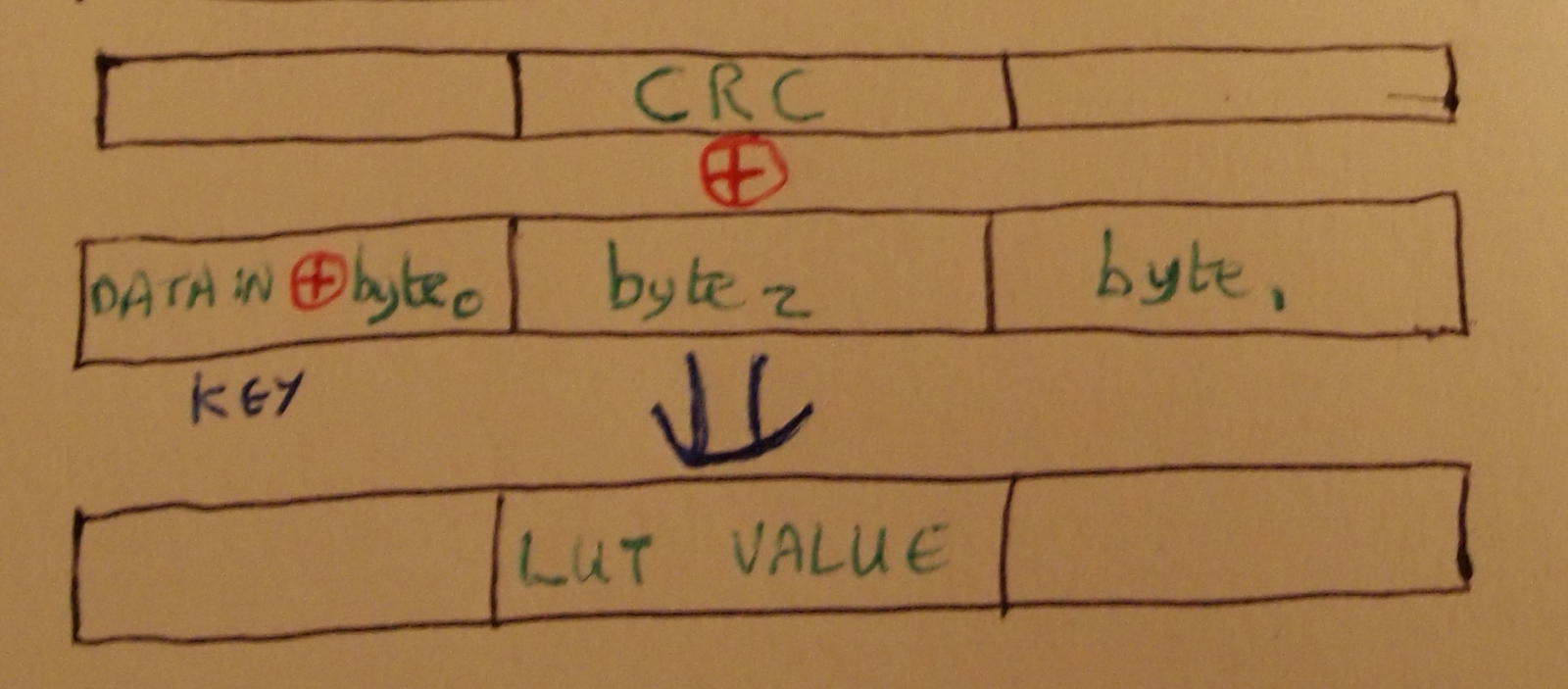
There is one easy way to determine the correct CLK1-6. If a packet has a payload that includes a Cyclic Redundancy Check (CRC), then we can use the CRC to verify that we have unwhitened the packet correctly. If one of our 64 possible CLK1-6 values results in a CRC match, then we win.
Up to this point, this method was described in BlueSniff: Eve meets Alice and Bluetooth.
The main problem with the CRC method is that it only works on packets that have CRCs. If you look through the Bluetooth Core Specification, you’ll find that only certain packet types have payloads with CRCs, and it turns out that these are the minority of Bluetooth packets in the wild. It is very common to see thousands of packets from a piconet without ever capturing one CRC with Ubertooth. Because of this, we needed another method to determine if a CLK1-6 value is correct or incorrect.
The next method we use to validate CLK1-6 is to perform a series of sanity checks on the packet format. The unwhitened packet header includes a four bit packet type field. If, for example, the packet type field is 5, then we know that it is an HV1 packet. HV1 packets do not have CRCs, but they have a payload encoded with a 1/3 rate Forward Error Correction (FEC) method implemented by repeating every bit three times in a row. Since different packet types use different FEC methods, we can perform a sanity check that verifies that every bit is repeated three times for the expected packet length (with some allowance for bit errors). If the FEC check fails, then we can be pretty sure we have the wrong CLK1-6 value.

Up to this point, this method was described in Building an All-Channel Bluetooth Monitor.
Unfortunately, CRC and sanity checks are not as useful as you might think. Originally we thought that we could simply look for correct CRCs, but they turned out to be rare. Then we thought that we could use a process of elimination where incorrect CRCs or sanity check failures would allow us to remove large numbers of candidate CLK1-6 values, but those cases also turned out to be less frequent than we thought.
The main reason we are often unable to eliminate a candidate CLK1-6 value is that Bluetooth has more than sixteen packet types, so the 4 bit packet type field in the header is overloaded. Here’s an example:
For a trial CLK1-6 value, the packet type field is decoded as 10. This could indicate that the packet type is DM3, a data packet carrying 2 to 123 data bytes and a CRC, or it could indicate that the packet type is 2-DH3, an Enhanced Data Rate (EDR) packet that uses a modulation for the payload that cannot be demodulated by Ubertooth One. (We can demodulate the packet header but not the payload.)
Without prior knowledge of the state of the piconet, we don’t know which of the two packet types is present. We assume it is a DM3 packet and check for a CRC. If we get a CRC match then we win, but this is rare. More often the CRC check fails. This means one of two things: Either the CLK1-6 value is wrong, or the packet is actually a 2-DH3 packet that we can’t verify. Since we can’t verify one of the possible reasons for CRC failure, we can’t eliminate that CLK1-6 value from our list of candidates.
Some of our CRC and sanity checks have a positive result indicating a correct CLK1-6. Some of them have a negative result indicating that the CLK1-6 value can be eliminated. However, the majority of our checks have an inconclusive result. This means that the process of elimination is rarely successful with just one packet.
Fortunately Bluetooth piconets tend to transmit packets fairly often, so we can continue the process of elimination across multiple received packets. Once we have the first packet, we can usually reduce the 64 CLK1-6 values to 50 to 60 candidates. With each subsequent packet, we can usually eliminate a few more candidates, but it is tricky.
The trickiness has to do with inter-packet timing. All packets are transmitted in time slots dictated by the master’s clock. We know how often the clock increments, and we have guesses as to the lower 6 bits of the clock. When we receive a subsequent packet, we can measure the time interval from one packet to the next and determine how many time slots have elapsed. This tells us how much to increment our original guesses when testing the new packet.
This would be a fairly reliable method if it were possible to have two clocks perfectly agree with each other. The crystal on Ubertooth One meets the requirements of the Bluetooth specification, so it is just as good as any Bluetooth device (with a frequency stability of 20 ppm). However, we don’t know how much faster or slower the target master’s clock is compared with the clock on the Ubertooth. It might be as much as 40 ppm different. Even if we had the best clock in the universe on Ubertooth, the target master’s clock will still drift by up to 20 ppm (assuming it is operating within spec).
Because of clock drift, we sometimes eliminate a candidate CLK1-6 value that might be correct simply because we counted the wrong number of time slots between packets. Additionally, bit errors in packets may cause us to incorrectly eliminate a candidate (e.g. if the bit error caused a CRC failure on a packet type without an overloaded packet type field). These things happen, and that’s why UAP discovery sometimes fails with zero candidates remaining. In these cases we simply start the process over as new packets arrive, and we usually get a correct result before having to restart very many times.
A nice enhancement to the code would be consideration of the maximum possible clock drift when computing time slot intervals. If we considered three intervals instead of one, for example, we might avoid a lot of cases where we improperly eliminate the correct CLK1-6 value. Additionally, we could benefit from keeping a running estimate of the master’s clock drift after we have determined the UAP.
A problem people sometimes have with Ubertooth is that the correct UAP is determined but is subsequently lost. This happens because a packet is received that doesn’t agree with the previously determined UAP, probably because of bit errors but possibly due to clock drift. Since we have an all-or-nothing approach to determining the UAP, a single disagreement can result in losing the correct value. Another nice enhancement would be maintaining a confidence value for the current UAP (or perhaps for multiple candidates). If a UAP has proven correct for 1000 packets, it would be nice not to throw it out when one packet disagrees. This would complicate some already convoluted code, but it is definitely worth trying.
Overall, we have a very effective method of determining the master’s UAP through passive monitoring. It is complicated, but it is only a small part of the even more complicated process of determining a piconet’s frequency hopping pattern and hopping along.


