Emulating a PS5 Controller with Cynthion
We’ve recently published the second video in our Cynthion training series, so if you want to go deeper into exploring and experimenting with USB, this is for you. In this video, Martin explains the basics and evolution of Facedancer and demonstrates how to use Cynthion and Facedancer to emulate a PS5 controller. If you haven’t already, check out the first video- Sniffing PS5 Controller Packets with Cynthion.
Sniffing PS5 Controller Packets with Cynthion
In our latest training video Martin uses Cynthion to sniff PS5 controller packets. The video guides you through how to set up Cynthion, how to use Packetry, and what PS5 controller packets look like. If you are just getting started with Cynthion or learning about USB, we suggest checking out this video.
Reverse-engineering a VNA ECal Interface With Cynthion
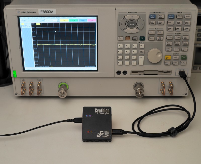
Recently I’ve been working on a little reverse-engineering project, hoping to make some of my electronics test equipment more convenient to use.
Often when doing reverse-engineering, a general strategy that I follow is to make (informed) guesses about how something might work and then I go looking for ways to prove that right or wrong. In this project, Cynthion was really useful for that process as I could use it to emulate part of the target system, so that I could quickly and easily test out theories about the protocol.
This write-up goes over some of the progress I’ve made so far and hopefully it will provide some helpful techniques you can use in your own projects!
Background
In my work and hobby projects, I’m often using a Vector Network Analyzer (VNA) to measure RF components. Ideally, on each power-up and whenever the measurement parameters are changed, the VNA should be calibrated by connecting and measuring a set of four standards in turn on each of the two measurement ports. This can get a little tedious if you need to re-calibrate often, so an alternative option is to use an Electronic Calibration module (ECal) which only requires one connection per port and then has internal switches to select between the different standards automatically. ECal modules are available for my VNA (an Agilent E8803A), but they’re rare and expensive, so I’d like to figure out how the VNA communicates with them so that I can implement it myself in an open-source ECal.
Reverse-engineering options
Of course, the easiest way to do this would be to connect an ECal module and capture the USB traffic (with Packetry!), but an actual ECal is too elusive.
The next option is to disassemble and analyze the software running on the VNA, which I spent a bit of time doing, but it was slow going as I’m not too familiar with the APIs on Windows and how it uses them for USB. However, there are some quick things to learn by looking at the software. It’s split into many DLLs, so it’s easy to see the imports and exports of each and get an idea of the functionality we might expect from the USB ECal:
$ winedump -j export ecalusb.dll
Contents of ecalusb.dll: 33280 bytes

[...]

  Entry Pt  Ordn  Name
  00001F50     1 ReadModule
  00002160     2 SetState
  00001F90     3 ReadModule1K
  000016D0     4 Reset
  00001FD0     5 ReadModuleData
  00002010     6 WriteModuleData
  00002210     7 EraseSector

Done dumping ecalusb.dll
So, it should have ways to read and write data on the module, which makes sense as it needs to store S-parameter data describing the characteristics of the different standards to be used for calibration. It also has SetState, which probably sets the switch positions to select different standards on each port.
Device Emulation
I decided to go down the route of emulating the ECal device, then seeing what the VNA tried to request of it and iterate from there. Using Cynthion with the Facedancer library you can easily emulate a USB device by writing a Python script, and quickly make changes to try out different things.
I started with the template.py example from the Facedancer project. Usually, a USB host will identify a particular device by looking at the vendor ID & product ID and/or the manufacturer/product/serial strings. From searching on forums and other test equipment groups, I found the expected values for the target device and I modified the template with these:
#!/usr/bin/env python3

from facedancer         import main
from facedancer         import *

@use_inner_classes_automatically
class ECalDevice(USBDevice):

    vendor_id                : int  = 0x0957
    product_id               : int  = 0x0001

    manufacturer_string      : str  = "Agilent Technologies"
    product_string           : str  = "USB ECal Module"
    serial_number_string     : str  = "S/N 12346"
    device_speed             : DeviceSpeed = DeviceSpeed.FULL

    class ECalConfiguration(USBConfiguration):

        class ECalInterface(USBInterface):

            class ECalInEndpoint(USBEndpoint):
                number               : int                    = 1
                direction            : USBDirection           = USBDirection.IN
                transfer_type        : USBTransferType        = USBTransferType.BULK
                max_packet_size      : int = 64

                def handle_data_requested(self):
                    self.send(b"Hello!")

            class ECalOutEndpoint(USBEndpoint):
                number               : int                    = 1
                direction            : USBDirection           = USBDirection.OUT

                def handle_data_received(self, data):
                    print(f"Received data: {data}")

main(ECalDevice)
Running this script and then clicking “Detect Connected ECals” on the VNA gives the following output:
$ python ecal-emulate.py --suggest
INFO    | __init__       | Starting emulation, press 'Control-C' to disconnect and exit.
INFO    | moondancer     | Using the Moondancer backend.
INFO    | moondancer     | Connected FULL speed device '__main__.ECalDevice' to target host.
INFO    | device         | Host issued a bus reset; resetting our connection.
INFO    | moondancer     | Target host configuration complete.
WARNING | device         | Stalling unhandled OUT VENDOR request 0x04 to DEVICE [value=0x0000, index=0x0000, length=0].
This shows that the script got a vendor-specific request from the VNA, but doesn’t yet have the code to handle it so it returns a STALL response (which is the terminology for how USB devices respond to unhandled requests).
Since I ran it with the --suggest argument, stopping the script gives me a suggestion for code that I can add to handle the request!
^CINFO    | moondancer     | Disconnecting from target host.

Automatic Suggestions
These suggestions are based on simple observed behavior;
not all of these suggestions may be useful / desirable.


Request handler code:

  @vendor_request_handler(number=4, direction=USBDirection.OUT)
  @to_device
  def handle_control_request_4(self, request):
      # Most recent request data: bytearray(b'').
      # Replace me with your handler.
      request.stall()
I add the suggested handler to my script, but change the response from stall to ack and also print out the request:
--- a/ecal-emulate.py
+++ b/ecal-emulate.py
@@ -34,4 +34,11 @@ class ECalDevice(USBDevice):
                def handle_data_received(self, data):
                    print(f"Received data: {data}")

+    @vendor_request_handler(number=4, direction=USBDirection.OUT)
+    @to_device
+    def handle_control_request_4(self, request):
+        print(request)
+        request.ack()
+
+
main(ECalDevice)
I ran the script and got a new message saying that there was also a vendor request number 2 to be handled, so I went through the same process to handle that too. After doing that, I got a lot more output - now it sent many #2 vendor requests with values counting down from 0x400 (1024) by 6 each time:
OUT VENDOR request 0x04 to DEVICE [value=0x0000, index=0x0000, length=0]
OUT VENDOR request 0x02 to DEVICE [value=0x0400, index=0x0000, length=0]
OUT VENDOR request 0x02 to DEVICE [value=0x03fa, index=0x0000, length=0]
...
OUT VENDOR request 0x02 to DEVICE [value=0x0010, index=0x0000, length=0]
OUT VENDOR request 0x02 to DEVICE [value=0x000a, index=0x0000, length=0]
OUT VENDOR request 0x02 to DEVICE [value=0x0004, index=0x0000, length=0]
This looked very promising, as I was expecting it to read out 1 kB of memory from the hints in some of the DLL exports mentioned earlier. However, I was a bit confused at this point because, while it seemed to be addressing the memory, I couldn’t see any way that the device could actually return the data. Due to the way USB control transfers work, there isn’t a way for an OUT request to return any data - it can only ACK or NAK.
I wanted to see if there might be something else happening on the bus that I might be missing. Fortunately, I have a few Cynthions about so I hooked up a second one in-line to do a packet capture and see if I could learn more:
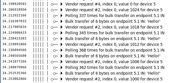
Doh! Of course, the template example I was working from was also setting up a BULK IN endpoint to return “Hello!”.
After each address vendor request, the VNA would request data on the bulk endpoint and receive those 6 bytes, then adjust the address accordingly and repeat.
If I had realised, I could have just added a print to the handler to see that happening rather than setting up the packet capture.
Now that I had a pretty good idea of how the data was being read out I could go ahead and implement it properly, but I needed some appropriate data to return.
Fortunately I was able to find some memory dumps that another user had shared online for the 8506x series ECal modules.
They had shared them as ASCII hex dumps, so I converted them to binaries with xxd:
$ head HP85062-60006.txt
=~=~=~=~=~=~=~=~=~=~=~= PuTTY log 2021.09.29 21:47:04 =~=~=~=~=~=~=~=~=~=~=~=
dump 0 040000

000000: 48 50 38 35 30 36 30 43 20 45 43 41 4C 00 E8 D1  | HP85060C ECAL... |
000010: 31 83 C4 02 64 00 4E 6F 76 20 32 38 20 31 39 39  | 1...d.Nov 28 199 |
000020: 34 00 FF FF FF FF FF FF FF FF FF FF FF FF FF FF  | 4............... |
000030: FF FF FF FF FF FF FF FF FF FF FF FF FF FF FF FF  | ................ |
000040: FF FF FF FF FF FF FF FF FF FF FF FF FF FF FF FF  | ................ |
000050: FF FF FF FF FF FF FF FF FF FF FF FF FF FF FF FF  | ................ |
000060: FF FF FF FF 30 30 33 36 37 00 31 C0 50 E8 88 08  | ....00367.1.P... |

$ xxd -r HP85062-60006.txt HP85062-60006.bin

$ hexdump -C HP85062-60006.bin | head
00000000  48 50 38 35 30 36 30 43  20 45 43 41 4c 00 e8 d1  |HP85060C ECAL...|
00000010  31 83 c4 02 64 00 4e 6f  76 20 32 38 20 31 39 39  |1...d.Nov 28 199|
00000020  34 00 ff ff ff ff ff ff  ff ff ff ff ff ff ff ff  |4...............|
00000030  ff ff ff ff ff ff ff ff  ff ff ff ff ff ff ff ff  |................|
*
00000060  ff ff ff ff 30 30 33 36  37 00 31 c0 50 e8 88 08  |....00367.1.P...|
00000070  33 35 46 33 35 46 20 4d  57 31 00 c4 04 56 e8 fb  |35F35F MW1...V..|
00000080  08 83 c4 02 38 20 41 75  67 20 32 30 30 31 20 00  |....8 Aug 2001 .|
00000090  41 47 49 4c 45 4e 54 2f  4d 54 41 00 b8 f8 6a eb  |AGILENT/MTA...j.|
000000a0  93 83 3e 94 06 00 74 1e  a1 82 06 83 c0 41 a2 98  |..>...t......A..|
Then I modified my Python script to load that file and return the data from the bulk endpoint, and tried again to detect the device from the VNA:
--- a/ecal-emulate.py
+++ b/ecal-emulate.py
@@ -14,6 +14,9 @@ class ECalDevice(USBDevice):
     serial_number_string     : str  = "S/N 12346"
     device_speed             : DeviceSpeed = DeviceSpeed.FULL

+    address = 0
+    data = open('EEPROM/HP85062-60006.bin', 'rb').read()
+
     class ECalConfiguration(USBConfiguration):

         class ECalInterface(USBInterface):
@@ -25,7 +28,10 @@ class ECalDevice(USBDevice):
                 max_packet_size      : int = 64

                 def handle_data_requested(self):
-                    self.send(b"Hello!")
+                    # Respond with 32 bytes of EEPROM data
+                    dev = self.get_device()
+                    addr = dev.address
+                    self.send(dev.data[addr:addr+32])

             class ECalOutEndpoint(USBEndpoint):
                 number               : int                    = 1
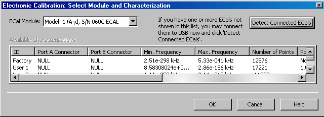
Success! …sort of. It detected something, which is great progress, but the output is a mess. After staring at it for a while, I realised my silly mistake - I’d forgotten to update the address when receiving vendor request 2:
--- a/ecal-emulate.py
+++ b/ecal-emulate.py
@@ -44,6 +44,7 @@ class ECalDevice(USBDevice):
     @to_device
     def handle_control_request_2(self, request):
         print(request)
+        self.address = request.value
         request.ack()
I added that, re-ran everything, and… nothing! It didn’t detect anything anymore. Something about that mistake actually made it work better.
Something that’s very common in file formats is to start with a header that includes some magic value and the parser will check that value before doing anything else. With the mistake in place, the script was returning the first 32 bytes of data to every request, so that was probably enough to pass the header check and show a detected device. However, that suggests that upon implementing the addressing, now the script wasn’t returning the header whenever the VNA was expecting it.
I had a look back at the pattern of #2 vendor requests:
OUT VENDOR request 0x02 to DEVICE [value=0x0400, index=0x0000, length=0]
OUT VENDOR request 0x02 to DEVICE [value=0x03e0, index=0x0000, length=0]
...
OUT VENDOR request 0x02 to DEVICE [value=0x0040, index=0x0000, length=0]
OUT VENDOR request 0x02 to DEVICE [value=0x0020, index=0x0000, length=0]
^CINFO    | moondancer     | Disconnecting from target host.
Two things stood out to me about those:
- The VNA starts by requesting with
value=0x400and then counts down - that’s a bit odd, I’d expect it to start at address 0 and count up. - The VNA never actually sends a request with
value=0x0, so the script never sends the header at all with the addressing in place!
This got me thinking that maybe there’s some quirk in the addressing and it should actually be reversed (so that a request with value=0x400 goes to address 0x0).
I made that change and re-ran the test:
--- a/ecal-emulate.py
+++ b/ecal-emulate.py
@@ -44,7 +44,7 @@ class ECalDevice(USBDevice):
     @to_device
     def handle_control_request_2(self, request):
         print(request)
-        self.address = request.value
+        self.address = 0x400 - request.value
         request.ack()
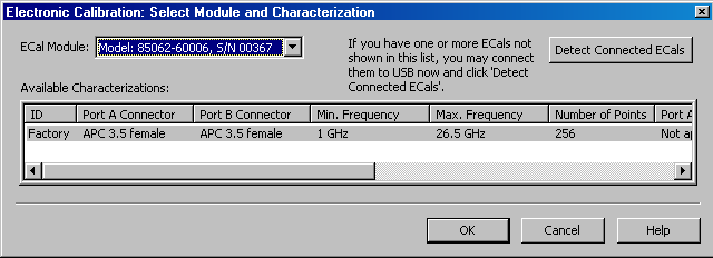
Bingo! The device is detected and all the information about it looks correct now.
While there are some other details still to figure out, I’ll wrap it up there as I think it’s demonstrated the process pretty well. Hopefully it provides some inspiration, please let us know if you use these techniques and tools in your own projects!
For anyone interested, the full code and any further research is available here: https://github.com/miek/ecal-reversing
Cynthion is Here!
We’re pleased to announce that Cynthion is now available for purchase from our authorized resellers! This FPGA-based hardware platform from Great Scott Gadgets powered by LUNA gateware is your new go-to tool for discovering and exploring the world of USB at a fraction of the cost of existing High Speed USB analyzers. Whether you’re experienced with USB or you’re new and learning about it, Cynthion is a great multipurpose addition to your hardware experimentation toolbox! We’ve also developed custom open-source software tools that work with Cynthion:
-
Packetry is a fast and intuitive open-source software that allows you to capture and analyze traffic between a host and Low-, Full-, or High-Speed USB devices.
-
Moondancer is a Facedancer backend that enables you to reverse engineer USB devices and even create your own!
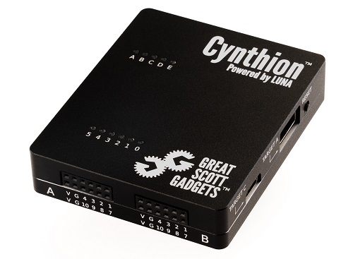
Cynthion comes in a beautiful and protective milled aluminum enclosure so that despite its small size (it fits in the palm of your hand) it has a solid feel and a nice weight. It is also currently available for sale without an enclosure at a lower cost. We’ve offered this option to make Cynthion as financially accessible as possible for hobbyists, students, and small teams.
You can learn more about Cynthion, including where to purchase it, by visiting our Cynthion webpage.
Cynthion is at Mouser
Note: This is a crosspost of a Cynthion update on Crowd Supply: https://www.crowdsupply.com/great-scott-gadgets/cynthion/updates/cynthion-is-at-mouser
An 885 lb / 401.43 kg shipment of thousands of Cynthions has been received by Mouser (who will fulfill Cynthion orders for Crowd Supply)! We expect the Cynthions to start shipping to backers around the 5th of July. You will receive a notice when your Cynthion has shipped.
While you wait for your shipping notice and for your device to arrive, take a moment to read the Cynthion documentation. Cynthion does not ship with USB cables, so take a look at the connection diagrams in this documentation for different use cases and make sure you have all the cables you will need.
As you receive your Cynthions we would love to see your first pictures with your device! Please tag Great Scott Gadgets on X, Mastodon, Instagram, or post in the #show-your-gsg channel in our Discord.
Cynthion Shipping Soon!
Note: This is a crosspost of a Cynthion update on Crowd Supply: https://www.crowdsupply.com/great-scott-gadgets/cynthion/updates/cynthion-shipping-soon
The first few Cynthions have come off of the manufacturing line! Once the first full batch of Cynthions is completed we will send them to Mouser who will ship them to you, our backers. Shipping will happen soon, so please make sure your address on Crowd Supply is up-to-date. If you need assistance with an address change please contact Crowd Supply. We will post another update once the first orders leave the Mouser warehouse. Until then, please enjoy these photos from our contract manufacturer.
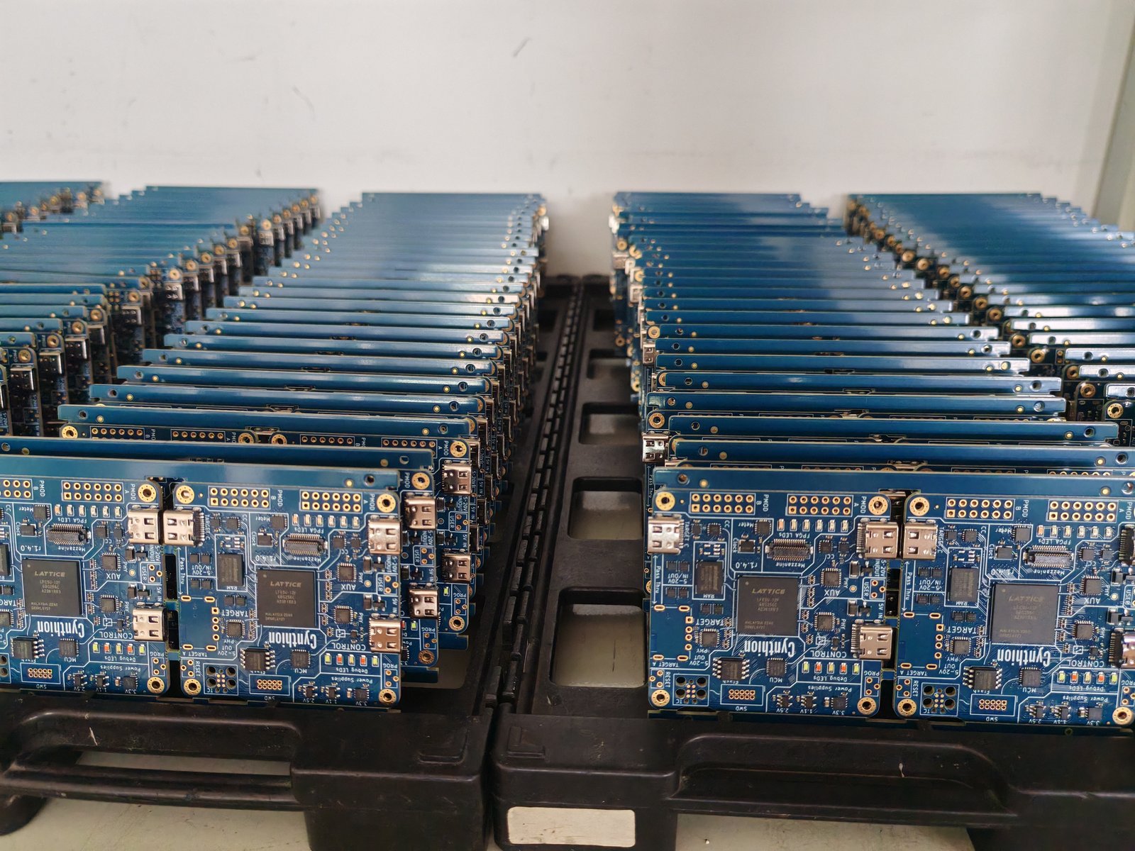
Batch of Cynthions before last USB component was soldered on.
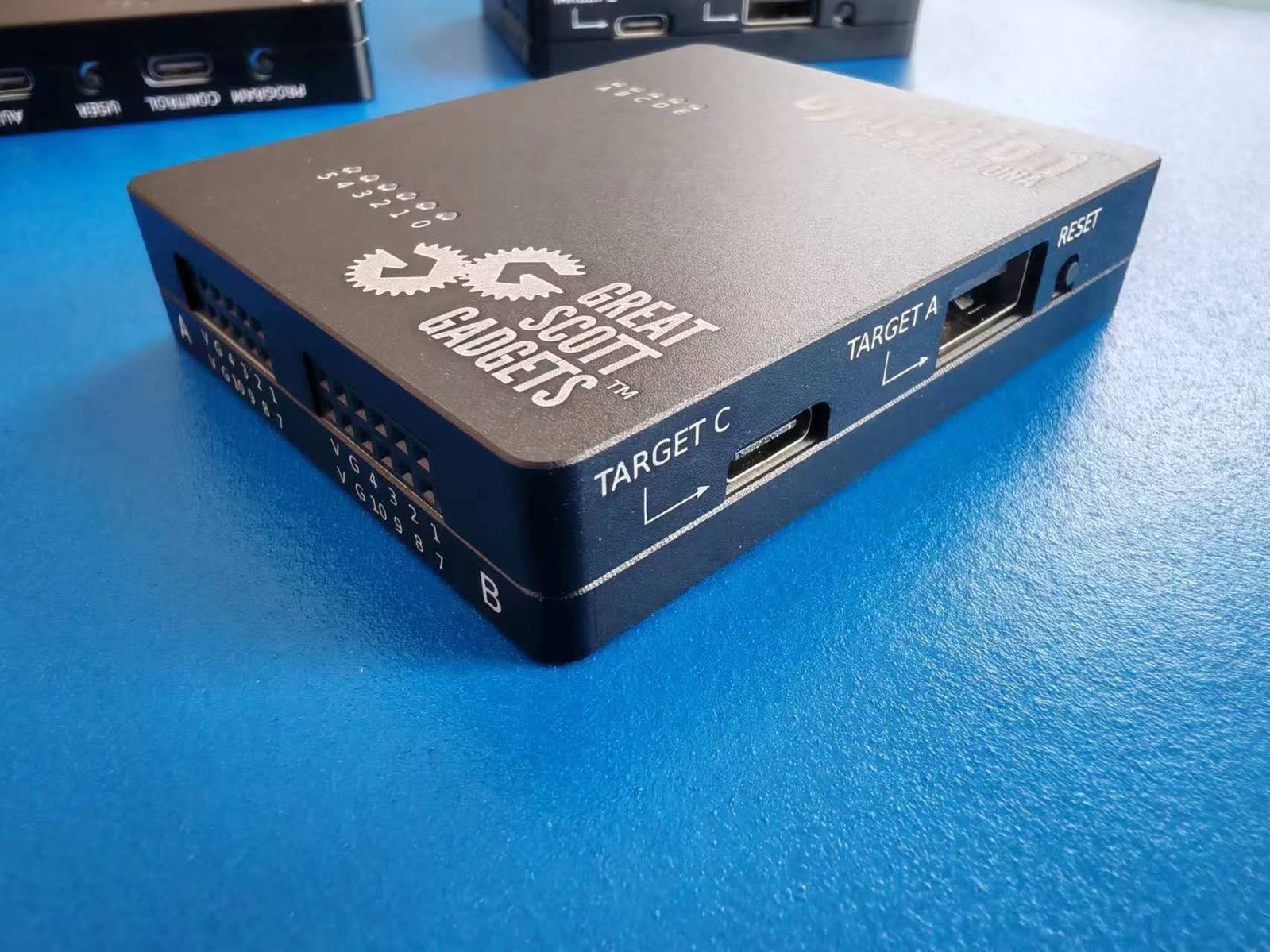
Enclosed Cynthion ready to ship
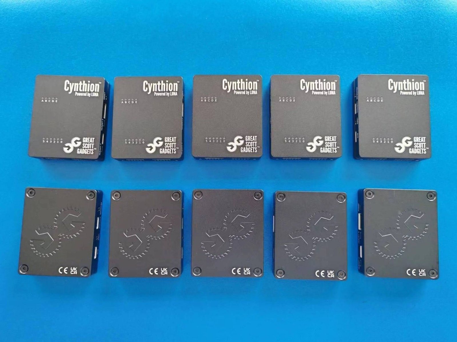
Batch of enclosed Cynthions ready to ship
Cynthion Manufacturing Progress
Note: This is a crosspost of a Cynthion update on Crowd Supply: https://www.crowdsupply.com/great-scott-gadgets/cynthion/updates/cynthion-manufacturing-progress
Cynthion update time!
Final samples have been manufactured, some of them have been sent for RoHS testing (and each of them has passed), and manufacturing is under way. Everything’s going great so far, and we’re on track for June shipping!
Here is your first glimpse of finished Cynthions in their enclosures and in the boxes we will be shipping them in.
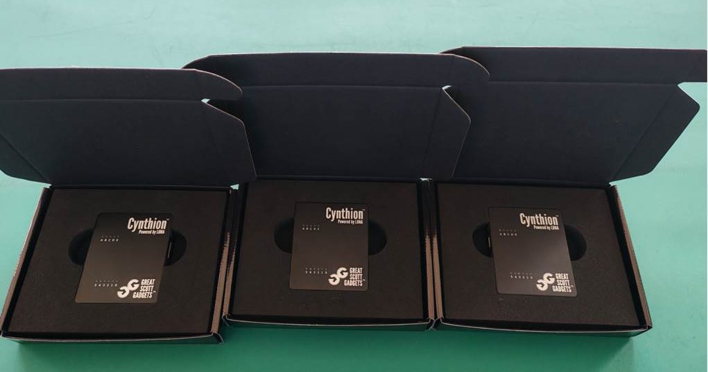
The significance of RoHS testing is that Cynthion had to pass that test in order for us to earn our CE marking, which allows us to sell Cynthion in the EU. RoHS stands for “Restriction of Hazardous Substances in Electrical and Electronic Equipment” and this directive requires that electronic and electrical equipment does not exceed certain thresholds for lead, cadmium, mercury, and other hazardous substances. RoHS testing is completed by a third-party lab and the lab we chose used “destructive testing methods” which meant that we had to send a few completed Cynthions, including enclosure and packaging, for them to destroy.
Cynthion Has Passed EMC and Tycho Has Shipped to Our Manufacturer
Note: This is a crosspost of a Cynthion update on Crowd Supply: https://www.crowdsupply.com/great-scott-gadgets/cynthion/updates/cynthion-has-passed-emc-and-tycho-has-shipped-to-our-manufacturer
The title says it all! Cynthion has passed EMC testing which means it is ready for manufacturing and Tycho, our Cynthion-testing quality assurance rig, has been shipped to our manufacturer. Our next steps are to work closely with our manufacturer to create final product samples, ensure the QA process is achieving the results we expect at factory level, and receive the final product samples and test them in-house here at Great Scott Gadgets. We’ll have more for you soon!
Cynthion Design Work Completed
Note: This is a crosspost of a Cynthion update on Crowd Supply: https://www.crowdsupply.com/great-scott-gadgets/cynthion/updates/cynthion-design-work-completed
We are happy to say that early this month we completed the design work for Cynthion! This milestone is the culmination of yet another three months’ worth of work. Since our October update we have:
-
revisited the EMC testing lab for another round of pre-compliance testing,
-
used the EMC testing results to improve signal integrity on Cynthion and produce another hardware revision,
-
ordered another revision of the Cynthion enclosure prototypes,
-
designed and ordered prototypes of the Cynthion packaging,
-
produced another Cynthion hardware revision to fix minor issues,
-
rearranged the Cynthion schematic,
-
updated documentation in Cynthion-related repositories,
-
ordered a production sample of Cynthion,
-
worked on the Cynthion manufacturing test jig and test scripts,
-
worked on apollo, luna, saturn-v, packetry, and Facedancer (all of which are used in conjunction with Cynthion or as part of manufacturing testing), and
-
scheduled another visit to the EMC testing lab for this week and taken Cynthion in for final evaluation.
Since we’ve only recently reached the milestone of finishing the design work, it means Cynthion delivery will be delayed until June to allow time for manufacturing and shipping. Here is what the current timeline to delivery looks like:
January
Since the completion of Cynthion’s design, we have pivoted to finishing up the hardware test jig (which we have named Tycho) that we will send to our manufacturer so they can test each Cynthion as it comes off the production line. Designing this test jig has required multiple revisions that have changed slightly with each revision of Cynthion. Since Cynthion is so unique in its design we have even had to develop custom cables for Tycho. This is a story we are looking forward to telling you all about once the Tycho team has completed their work.
February
Our manufacturer is based in China and they will be unavailable almost all of February due to Chinese New Year celebrations. We will spend this month continuing to work on Tycho, documentation for Cynthion and related projects, and improving software, firmware, and gateware. By the end of this month we will ship Tycho to our manufacturers.
March
Cynthion will be in manufacturing for month one of two. In this month our manufacturers will produce the Cynthion PCBs, enclosures, and packaging. PCB production is expected to take about 2-3 weeks. As soon as the PCBs are produced, we will get a few production samples from the manufacturer for extra verification and testing by our team at Great Scott Gadgets. During this month we at Great Scott Gadgets will continue working on all of the Cynthion-related repositories and documentation.
April
Cynthion will be in manufacturing for month two of two. In this month Cynthions will be assembled, tested, and packaged by our manufacturer. Like March, we at Great Scott Gadgets will continue working on all of the Cynthion-related repositories and documentation. Additionally we will provide technical support to the manufacturing test team.
May
Cynthions will be on their way from our manufacturer in China to Crowd Supply’s fulfillment partner (Mouser) in the United States. At minimum this is expected to take two weeks, but we have scheduled an entire month for shipping as there can be lengthy customs delays when shipping internationally. This means that if there are no customs delays you may get your Cynthion sooner! Wish us luck.
June
The moment you’ve been waiting for! Cynthions will be shipped to you! If you have moved, you’ll want to make sure that you’ve updated your address on Crowd Supply before this point. Don’t worry, we will post an update before June reminding you to update your address.
Improvements to Cynthion Hardware
Note: This is a crosspost of a Cynthion update on Crowd Supply: https://www.crowdsupply.com/great-scott-gadgets/cynthion/updates/improvements-to-cynthion-hardware
Since our last hardware design update in April, we have been hard at work refining the Cynthion design in preparation for production. Believe it or not, we’ve completed and tested six design revisions since r0.6 described in April!
In r0.7 we increased the maximum pass-through current by selecting FETs with lower resistance and by improving heat dissipation of the PCB layout. We added filters to the buttons, reducing the need for debouncing in firmware and gateware. We added a zero ohm series resistor to the oscillator so that it could be replaced easily with a higher resistance if indicated by electromagnetic compatibility (EMC) testing. We also updated several component selections and added or removed various pull-up and pull-down resistors, ensuring that we follow recommendations for the FPGA and microcontroller.
After testing these improvements, we decided that the design was ready for pre-production. We updated a few component selections, refined some nuances of the PCB layout, and bumped the hardware version number from r0.7 to r1.0.0.
Hardware Semantic Versioning
At this time we adopted an internal standard for hardware semantic versioning. It can be difficult to know how to version hardware designs, so we chose to make our decision process easier by establishing a set of rules adapted from the popular semantic versioning standard for software. While the software semantic versioning standard is focused on the software’s Application Programming Interface (API), our standard for hardware focuses on the hardware/software interface.
As an example, a change to the PCB layout that has no affect on software would warrant a bump from 1.0.0 to 1.0.1, but swapping pin assignments on a microcontroller (necessitating different firmware behavior) would require the version number to be bumped from 1.0.0 to 1.1.0. While software version numbers are often prefixed with “v”, we use “r” for hardware, making it easier to tell if we are referring to a software version or hardware version.
Although r1.0.0 differed very little from r0.7, we bumped the major version number to indicate that it was the first version handed off for volume production. It later turned out that further revisions were required, but r1.0.0 was the first version that conceivably could have ended up in your hands.
The Component Shortage Strikes Again
As mentioned in Cynthion Delivery Timeline Update, we soon learned that the power monitoring component used in r0.6 through r1.0.0 was no longer available. While many thousands were available just three weeks earlier, they all had vanished in the short time between prototyping r0.7 and purchasing components for production!
Fortunately, we were able to find just enough of an alternative component, so we snatched it up and designed and tested another revision, r1.1.0, using the new part. Because the new part is the same IC in a different package, nothing needed to change in r1.1.0 except for the PCB layout and some pin assignments.
Around this time, we received new enclosure samples, updated for the larger PCB size introduced in r0.6. The samples were great, but we noticed that they made the buttons feel inconsistent. It was very difficult to center the PCB in the enclosure such that the button plungers all extended the same distance. A certain amount of play in the placement of the PCB within the enclosure is unavoidable, but for some reason it seemed to be nearly impossible to center the PCB perfectly.
Upon further investigation, the problem turned out to be with the PCB design, not the enclosure. When I had added a new button in r0.6, I accidentally placed it 0.1 mm closer to the PCB edge than the other two buttons. It wasn’t noticeable at first, but, once the board was placed in an enclosure, it was possible to feel the difference! We corrected this tiny discrepancy in r1.1.1.
Electromagnetic Compatibility Challenges
After our first round of EMC pre-compliance testing we hoped that we would be able to pass a second round with some software modifications and minor hardware updates (such as increasing the value of the oscillator series resistor). While some of these measures were effective, they weren’t enough to pass the emissions test. After our second test we determined that another hardware design revision was required to reduce electromagnetic emissions.
In r1.2.0 we significantly improved power supply connectivity and decoupling for the FPGA which seemed to be the principal remaining source of emissions. Most of these changes were enabled by updating the PCB from four layers to six. Additionally we added series resistors to the ULPI bus that connects each USB PHY to the FPGA. We suspected that these resistors may be unnecessary (except perhaps the ones on the ULPI clock signals), but it is much easier to swap in different resistances than it was before we added those resistor array footprints.
Our next pre-compliance test clearly indicated that we had successfully quashed emissions from the FPGA, but the we still had a borderline result. One of our configurations passed the test but with very little margin. We felt that we needed to reduce emissions further to ensure success in the formal test.
With the FPGA noise out of the way, it had become possible to detect emissions from the USB PHYs. After some experimentation, we determined that these emissions could be reduced with further modifications to the PCB design and enclosure.
We addressed PHY noise in r1.3.0 by improving shielding and PHY power supply decoupling and by installing common-mode chokes on the USB data signals. Additionally we made a change to FPGA control that makes it easier to recover a Cynthion bricked by bad gateware, and we fixed a power supply start-up bug that was introduced in r1.2.0.
I’m pleased to report that r1.3.0 passed EMC pre-compliance testing! There are some small bugs that need to be corrected in one more hardware revision, but we are now confident that Cynthion will pass the formal EMC test.
Viewing the Design
Most of the changes since r0.6 are unlikely to ever be noticed by a Cynthion user, but they all enhance the quality of the product in some way. The most significant functional change is that pass-through power now supports up to 3 A of current.
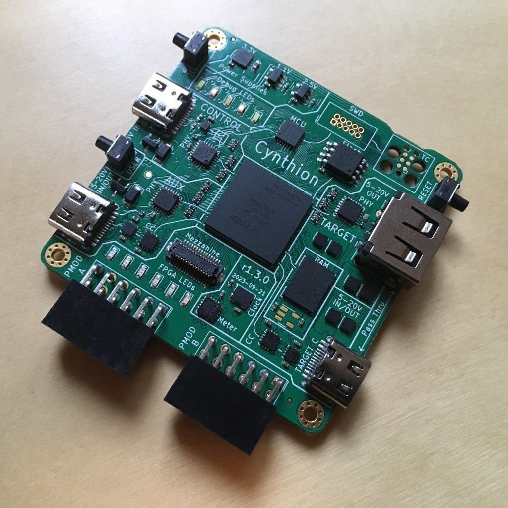
Design documents and fabrication outputs for each of these hardware revisions have been released in the new cynthion-hardware repository. Previously the design was included in the LUNA repository which now contains only the LUNA gateware library.
Moondancer: A Facedancer backend for Cynthion
Note: This is a crosspost of a Cynthion update on Crowd Supply: https://www.crowdsupply.com/great-scott-gadgets/cynthion/updates/moondancer-a-facedancer-backend-for-cynthion
One of the core features promised in the Cynthion announcement is the ability to create your own Low-, Full- or High- speed USB devices using the Facedancer library – even if you don’t have experience with digital-hardware design, HDL or FPGA architecture. If you’ve been eagerly anticipating this feature, we’re pleased to introduce Moondancer, a new Facedancer backend for Cynthion.
What is Facedancer?
Facedancer is a host-side Python library for writing programs that remotely control the physical USB port(s) on Facedancer boards such as the original Facedancer21, GreatFET One, and Cynthion.
Using Facedancer to control a physical USB port gives you direct control over the data encoded in USB streams and allows you to do things like:
- Emulate a physical USB device such as a keyboard, mass storage device, or serial interface,
- Act as a programmable proxy between a device and its host with the ability to inspect and modify the data stream,
- Fuzz host-side USB device drivers by deliberately sending malformed data that can trigger faults in the device or host software.
Facedancer Example
Let’s say you need to automate the operation of a computer running some software that can only accept input via keyboard:

A USB keyboard connected to the Target Operating System.
By connecting a Facedancer board such as Cynthion to the computer (called the “target”) in place of the USB keyboard, you can now use a second computer (called the “host”) to run a small Python script to control USB traffic between the target computer and Cynthion:
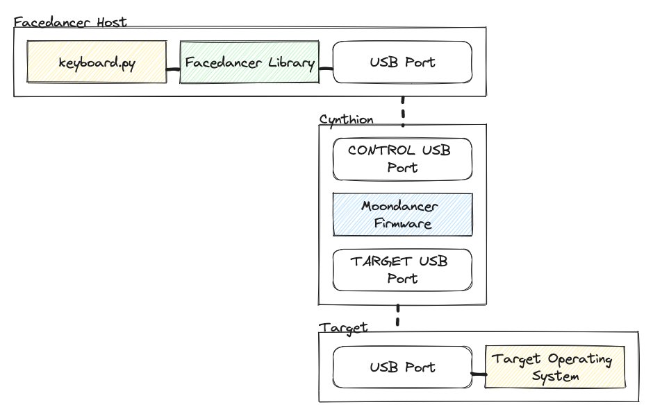
A Facedancer emulation of a USB keyboard connected to the Target Operating System.
Whenever a new USB peripheral is plugged in, the target operating system will first send a standard set of USB enumeration requests to the peripheral asking it to identify itself to the operating system. In the diagram above, Cynthion is the peripheral receiving enumeration requests from the target. However, instead of replying directly, Cynthion will forward any enumeration requests it receives to the Facedancer host. The Facedancer host will then respond to the target with a set of USB descriptors corresponding to the peripheral you are emulating. Once the target operating system has received a set of known USB descriptors, it will load the appropriate device driver for controlling the USB peripheral. All subsequent USB transfers initiated by the device driver will also be received by Cynthion and forwarded to the Facedancer host. By using a Facedancer emulation that responds appropriately to the command set of the peripheral being emulated, Cynthion can respond to the target operating system as if it were any actual physical device.
In our example, we can use Facedancer’s USBKeyboardDevice object to provide the USB descriptors and transfer commands required for a keyboard that follows the USB human interface device class specification:
import asyncio
from facedancer.devices.keyboard import USBKeyboardDevice

device = USBKeyboardDevice()

async def type_on_keyboard():
    # Type ls.
    await device.type_letters('l', 's', '\n')

main(device, type_on_keyboard())
What is Moondancer?
Moondancer is a new backend for Facedancer that adds support for Cynthion.
Facedancer supports a variety of boards by providing different backends for each supported board. For example, GreatFET One uses a backend called “greatdancer” while RPi + Max3241 boards use the “raspdancer” backend. In keeping with Cynthion’s lunar origins, we decided to call the new backend “Moondancer”.
What makes Cynthion different from other Facedancer-compatible boards is that, instead of being based on a microcontroller, it is built around an FPGA connected to three USB 2.0 PHY chips under control of the open source LUNA USB gateware library. While this provides us with more direct access to USB signals and their behaviour it also represented a significant engineering challenge for our team. The most significant challenge was how to control the USB controllers. On previous Facedancer devices, the controllers have been under software control via device firmware running on the device CPU. However, being an FPGA-based platform, Cynthion does not have a CPU!
At first glance, we had two choices for controlling the USB 2.0 PHY chips:
- Implement the control logic as gateware.
- Integrate a microcontroller into the Cynthion hardware design.
In principle a Facedancer device merely acts as a forwarder between the USB controllers and the controlling host. This means a gateware implementation could be as simple as exposing the registers controlling LUNA’s “eptri” triple-fifo endpoint peripheral via a set of USB Vendor Class commands. On the other hand, integrating another microcontroller into Cynthion would increase the design complexity significantly and add substantially to the bill of materials cost. All things being equal, we may have ended up with a gateware implementation were it not for the recent emergence of high quality, libre-licensed RISC-V implementations. Hosting a microcontroller as a “soft-core” on an FPGA is not a new idea but RISC-V’s open Instruction Set Architecture (ISA) removes many barriers to implementation such as licensing, compilers and tools. Therefore, while a Facedancer device implementation in gateware would be a very cool hack indeed, we thought it would be even cooler to take an approach that would also let you use Cynthion as a tool for getting started with RISC-V, System-on-Chip (SoC) design, and Embedded Rust while exploring USB in embedded environments.
How does Moondancer work?
Moondancer consists of several distinct components:
- moondancer-soc: A custom RISC-V SoC that integrates a libre-licensed RISC-V CPU with the LUNA USB peripherals.
- lunasoc-pac and lunasoc-hal: Embedded Rust support crates for moondancer-soc peripherals.
- smolusb: A lightweight, low-level USB stack appropriate for LUNA USB device controllers.
- Moondancer firmware: The device-side implementation of the Facedancer command protocol.
- Moondancer backend: The host-side Facedancer backend for communication with the Moondancer firmware.
moondancer-soc
At the heart of Moondancer lies a stripped-down RISC-V SoC design described in the Amaranth Hardware Description Language (HDL):
- SpinalHDL VexRiscV CPU
- Full RV32IMAC instruction set support
- 60 MHz clock speed
- 64 kilobytes of SRAM
- 4 kilobytes L1 instruction cache
- 4 kilobytes L1 data cache
- 2x GPIO peripherals
- 6x LED peripherals
- 1x UART peripheral
- 1x Timer peripheral
- 3x LUNA USB eptri peripherals
While the feature set may be modest in comparison to most commercial micro-controllers, the full gateware source of every single component integrated within the design is libre-licensed with all four freedoms intact.
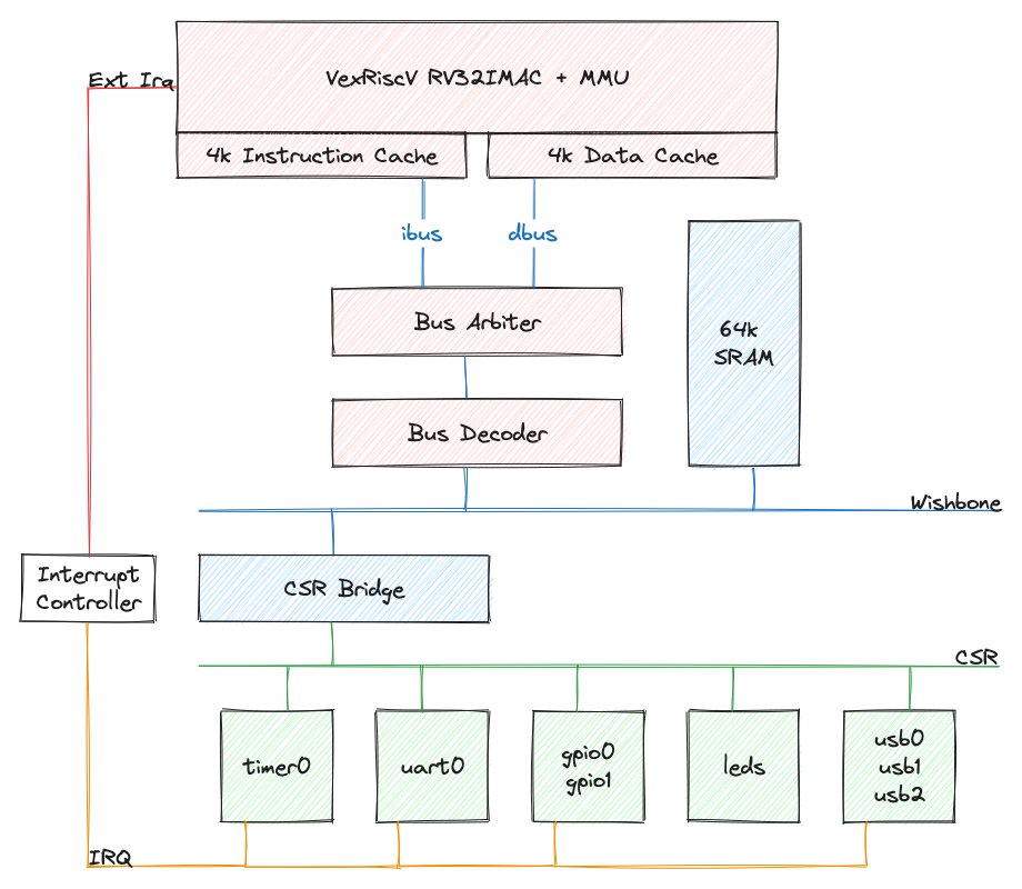
Moondancer SoC Architecture
After bringing up our “hardware” platform for the Moondancer firmware, we faced another set of challenges. In commercial SoC development, there are usually multiple teams tasked with creating the tooling, device drivers and development libraries for a new design. While we would still have to develop device drivers and libraries, we did not need to create yet another fork of GCC to implement our own custom toolchain with compiler, debugger, linker, and sundry utilities. Thanks to the efforts of many contributors, both commercial and from the broader community, the GNU toolchain has been shipping RiscV support for some time now, and Rust (via LLVM) can compile binaries for many RiscV variants right out of the box.
None of this would have been possible even a few years ago, and it is thanks to the efforts of a wide community that we were able to do it within the time and resources available to us:
lunasoc-pac
One of the fundamental building blocks in any Embedded Rust project is a Peripheral Access Crate (PAC) which provides safe register-level access to the processor’s peripherals. While there are already existing PACs and even HALs for RISC-V chips from companies such as Espressif and AllWinner there existed no equivalent for working with a custom-defined SoC implemented as gateware.
Fortunately, what most Rust PACs have in common is that their code is largely generated from an SVD description of the processor and its peripheral registers with the help of the svd2rust tool. Therefore, we extended the luna-soc library with the ability to export SVD files generated directly from the SoC design allowing anyone to easily generate a PAC for any luna-soc design.
lunasoc-hal
While it is entirely possible to develop an entire firmware using just a PAC crate, it would be nice to offer a friendlier programming interface and the possibility of code re-use across different processors. Normally, a chip will come with some form of vendor-provided HAL that provides higher-level abstractions for communicating with the peripherals and some compatibility with other products in the vendor’s product line. The Embedded Rust community took a slightly different approach to this problem with the embedded-hal project which provides a set of centrally defined traits to build an ecosystem of platform-agnostic drivers.
By adopting embedded-hal for our luna-soc design, we’ve made it possible for other luna-soc users to easily target their own custom designs even if the underlying peripheral implementations differ. It also means the Moondancer firmware can be more easily ported to any other platform with an embedded-hal implementation.
smolusb
Given that Facedancer requires direct access to the USB peripheral to perform emulation, and our SoC only has 64 kilobytes of RAM, we’ve developed ‘smolusb’, a new lightweight device-side USB stack that provides:
- a set of traits for implementing HAL USB device drivers
- data structures for defining device descriptors
- data structures for defining class and vendor requests
- device enumeration support
‘smolusb’ does not require Rust alloc support, uses a single statically allocated buffer for read operations, and supports zero-copy write operations. It supports high-level operations such as device enumeration but also provides several “escape hatches” that allow for direct control of the underlying peripheral for the purposes of device emulation and other Facedancer features.
Moondancer firmware and backend
Moondancer manages the communication between the Facedancer library and the remotely controlled USB peripheral and is split into two components:
- Moondancer firmware written in Rust and running in the SoC on Cynthion. The Moondancer firmware implements the Facedancer command set and controls Cynthion’s USB ports.
- Moondancer backend written in Python and running on the host. The Moondancer backend handles all communication between Facedancer and the Moondancer firmware.
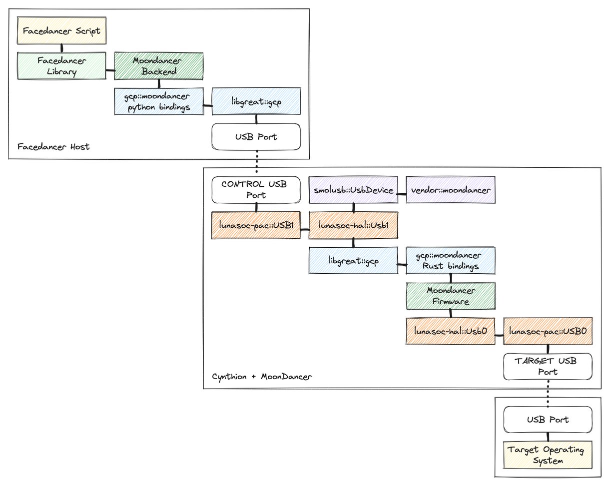
To mediate communication between the Moondancer backend and the Moondancer firmware we’ve used a Rust implementation of the same libgreat RPC protocol used by GreatFET and other Great Scott Gadgets open-source projects. The power of libgreat is its ability to generate and expose simple explorable APIs via Python, allowing for flexible communications between computers and embedded devices, embedded drivers, and more without having to get into the murky details of driver development, transports or serialization protocols. We hope this design decision will also allow others to more easily develop and integrate their own custom firmware for embedded USB applications with host software!
On the host side, the Moondancer backend is responsible for translating calls from Facedancer into libgreat commands which are then received on Cynthion’s CONTROL USB port, deserialized by libgreat and forwarded to the Moondancer firmware which is responsible for operating the Cynthion’s TARGET USB port.
Finally, the Moondancer firmware implements the Moondancer API for directly controlling the USB peripheral via operations to manage port connections, reset the bus, set the device address, manage endpoints, and send/receive data packets.
Wrapping up
If you have access to Cynthion hardware and would like to try out Moondancer please feel free to check out the Cynthion repository. Also, if you’re interested in custom SoC development and Embedded Rust, you can check out the luna-soc repository. Most of the non-USB functionality has also been tested on other ECP5 devices so, with a little bit of luck, you might be able to get something going with your favorite development board.
Acknowledgements
We would like to express our sincere gratitude to two individuals without whom Moondancer would not have been possible.
In particular, our work builds on the research of Travis Goodspeed who developed the original Facedancer board and software, and Kate Temkin who extended the software and generalized it for other platforms.
You can learn more about the history of Facedancer and LUNA in our fifth Crowd Supply update: “The History of LUNA”.
Cynthion Delivery Timeline Update
Note: This is a crosspost of a Cynthion update on Crowd Supply: https://www.crowdsupply.com/great-scott-gadgets/cynthion/updates/cynthion-delivery-timeline-update
Hello, campaign backers and other supporters of Cynthion and Great Scott Gadgets! In this update, we hoped to tell you that manufacturing was in progress and that we were getting close to delivering the first Cynthions to you. Unfortunately, we have encountered more delays while getting the hardware ready to go to manufacturing.
The first delay was caused by another component availability barrier, which is now solved. After our last hardware update, we placed an order with our contract manufacturer for the additional components added to the Cynthion hardware design in r0.6. At the time of engineering r0.6, all of the new components added in this major revision were widely available, and we had no indications that there would be issues acquiring them. However, when we received the BOM quote for these additional components from our contract manufacturer, we learned that the power monitor part we had planned to use, PAC1954T-E/J6CX, was no longer in stock, and the quoted lead time was 20 weeks. Focused on getting the product delivered to you on time, we ordered a substitute part right away, and our engineering team immediately got to work on another hardware revision to instead use a PAC1954 package that was in stock, PAC1954T-E/4MX. This revision was relatively minor, but we did have to order another round of prototypes for verification and testing. Each time we order and test a new round of prototypes, the process takes 3-4 weeks. We named this new Cynthion revision r1.1.0 and went to an independent test lab for the necessary pre-compliance testing before ordering the production PCBs.
Before going to manufacturing or putting Cynthion on the market, we must certify that the final product conforms with applicable regulations and standards in all the countries we will be shipping to. One of the important standards Cynthion must comply with is electromagnetic compatibility (EMC). Cynthion’s compliance with EMC includes two components: emissions and immunity. Emissions compliance means that the Cynthion won’t emit electromagnetic interference (EMI) that can adversely affect other devices in its environment, and immunity compliance ensures that the Cynthion itself won’t be affected by electrostatic discharge (ESD). So far, we have had two rounds of testing in an independent EMC testing lab, each evaluating Cynthion on the emissions and immunity standards we’ve identified as applicable to Cynthion. In the first round of testing, Cynthion passed neither emissions nor immunity tests. By the second round, a couple of weeks later, the engineering team had solved the immunity problems, and Cynthion passed with flying colors– no such luck with the emissions portion of the test.
Since then, we have worked very hard to solve the EMC emissions issues with Cynthion. The engineering team identified software and gateware modifications that significantly reduced emissions and also found some small hardware changes that helped. Although great progress was made in a short period of time, it became apparent that a new hardware revision (r1.2.0) would be required to test modifications that we think will clear the final hurdle. As of today, we are waiting for another round of prototypes to be delivered so that we can test the new revision, and we hope that these will be the pre-manufacturing prototypes that will successfully pass EMC at the lab.
Although it is only possible to precisely estimate when Cynthion will ship once we have solved the emissions issues and manufacturing is underway, you will see that the expected delivery date for Cynthion fulfillment has changed to January 31st, 2024, which is our best estimate. In this new proposed timeline, we allow ourselves another month to resolve the EMC emissions issues and pass pre-compliance testing. After that, we estimate that manufacturing and quality control testing will take about three months, and we are allowing another two months for logistics and fulfillment. We will have a better idea of whether this timeline is realistic or not after the next round of EMC pre-compliance testing at the independent lab, and we will be sure to update you again if things change again with the timeline. In the meantime, we assure you that delivering Cynthion to you is our priority, and thank you for your patience as we continue to work hard to accomplish this goal we have been working towards for so long. Please accept our apologies for not updating you as often as we’d like to. The engineers who are best equipped to write these updates are very busy working on getting Cynthion to you as soon as possible!
Updated Cynthion Enclosure
Note: This is a crosspost of a Cynthion update on Crowd Supply: https://www.crowdsupply.com/great-scott-gadgets/cynthion/updates/updated-cynthion-enclosure
About a year ago, we announced an FPGA substitution on the Cynthion project due to supply chain issues. Since then, the Great Scott Gadgets team has redesigned and enlarged the Cynthion board to accommodate the larger FPGA, and Timon has adapted the enclosure to fit the larger board.
The updated Cynthion enclosure measures 60 mm (2.36 inches) in width, 72 mm (2.83 inches) in length, and 15 mm (.59 inches) in height. The weight of the enclosure with a Cynthion inside and all hardware, comes to 99.5 grams. In comparison to the previous enclosure, the new one is 8 mm wider, 7 mm longer, 1 mm taller, and 3.5 grams lighter due to extra milling for Pmod connectors and other small changes.
Once I received the 3D model files from Timon, I got to work designing the final graphics for the Cynthion enclosure, which are shown in the image below.
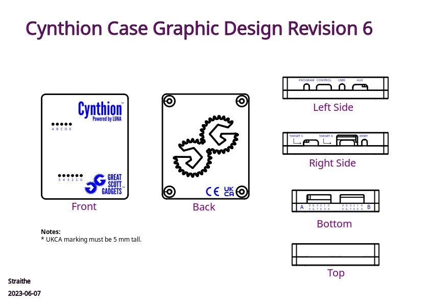
In this image, the black lines are the edges of the enclosure, connector holes, and hardware holes. The blue text and images are the graphics and labels that will be etched into the case. Once etched, these graphics will appear white-grey in colour. A rendering of the case is below:
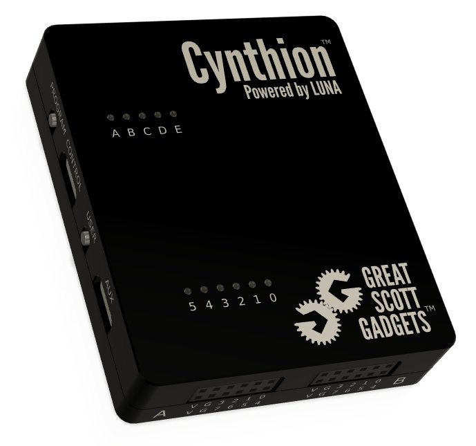
The differences from our early enclosure design include a complete change in graphics on the top of the case, moving the port labels to the edges, adding labels for the Pmods, and a debossed (not etched!) Great Scott Gadgets logo on the back.
Cynthion Hardware Design Update
Note: This is a crosspost of a Cynthion update on Crowd Supply: https://www.crowdsupply.com/great-scott-gadgets/cynthion/updates/cynthion-hardware-design-update.
We’ve completed the Cynthion r0.6 design! As mentioned in previous updates we needed to modify the design to accommodate new components due to supply chain issues. In this revision additional changes were made to resolve some problems beta testers identified with both power input and power output.
Issues Found During Beta Testing
Power input issues: When you plug Cynthion into a host computer, it is expected that Cynthion powers up and that the host computer will recognize that a device has been attached. Our beta testers found a couple of situations in which those things would not happen reliably. These scenarios were caused by a confirmed issue with excessive reverse leakage through a diode and a suspected issue with loading of the CC pins on the USB Type-C connectors.
Power output issues: Cynthion can pass power from a host computer (either the control host or a target host) through to a target device. Although this worked reliably, there was a problem that caused excessive power consumption and another problem that could theoretically damage a component on Cynthion.
Rethinking Power Distribution
As we investigated various power input and output issues over the past year or so, we sketched solutions planned for r0.6. When it came time to design r0.6, however, we realized that those solutions were insufficient.
Additionally, we realized that older versions of Cynthion were vulnerable to damage from high voltage input on any of the USB Type-C connectors. Originally designed with Micro-B connectors, Cynthion was later updated with Type-C connectors, introducing a much greater probability of accidental high voltage.
Micro-B connectors are intended to carry 5 V power, but Type-C connectors were designed to support up to 20 V, later extended to 48 V. USB hosts and power supplies are supposed to supply only 5 V unless the device asks for a higher voltage, but a noncompliant implementation could supply up to 20 V without negotiation.
Partly out of concern for overvoltage, we had implemented very limited Power Delivery (PD) capabilities in previous hardware revisions, minimizing the probability of input voltages higher than 5 V. However, our PD implementation may have contributed to other problems, and it did nothing to protect Cynthion from overvoltage from a noncompliant power supply.
We decided to completely rethink both power input and power output. After multiple rounds of design, simulation, and test, we’re happy to report that Cynthion’s capabilities are better than ever before!
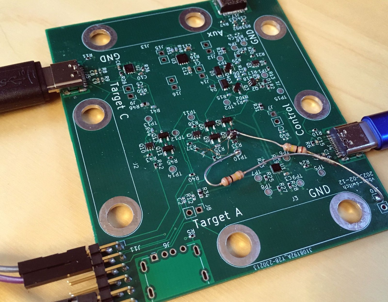
image caption: a prototype board, essentially a Cynthion with everything removed except power distribution and monitoring
What’s New in r0.6
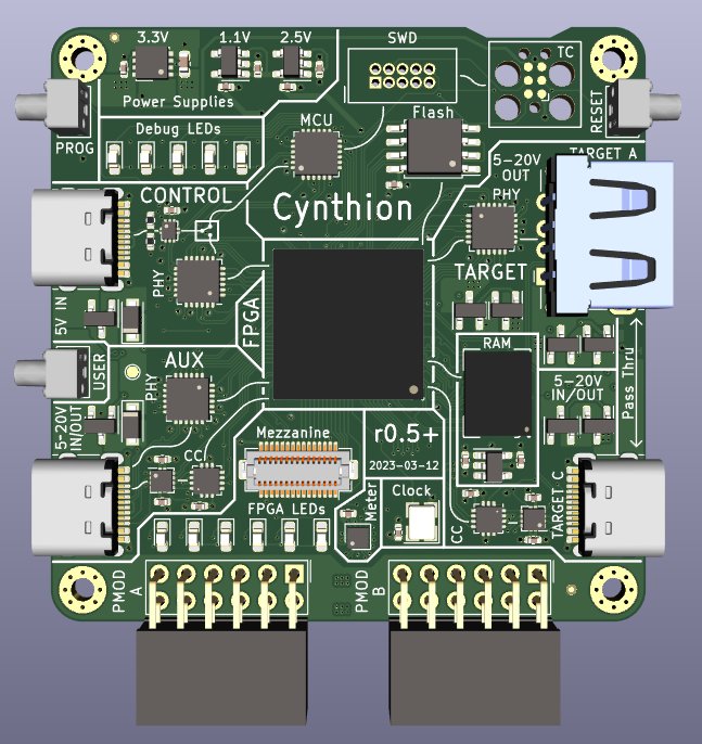
The USB ports are now renamed:
-
CONTROL is the primary port for control of Cynthion. Both the FPGA and the on-board debugger are now controlled over this port, so a second connection to the control host is no longer required.
-
TARGET C connects to a target host.
-
TARGET A connects to a target device and is directly connected to TARGET C, passing through data signals and allowing USB analysis.
-
AUX is an auxiliary port that can be used for various purposes, including MitM or as a secondary control port for development.
Cynthion now supports power passthrough up to 20 V, the highest voltage allowed in PD’s Standard Power Range (SPR). Power can now pass through to the AUX port in addition to the TARGET ports. PD’s Extended Power Range (EPR) is not supported.
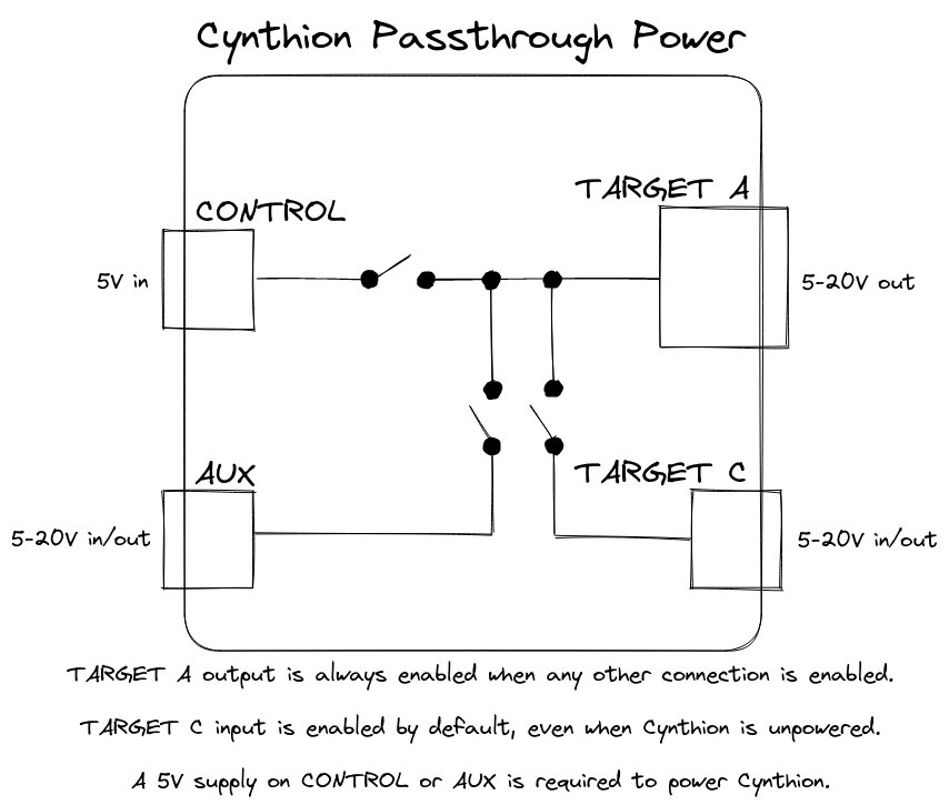
A 5 V power supply is still required on either CONTROL or AUX to power Cynthion itself, but the hardware now allows the user to select which port to use if 5 V supplies are available on both ports. Overvoltage protection automatically shuts off either input if it exceeds 5.5 V.
Power input and power passthrough are now two separate functions, no longer entangled with one another. All power output is strictly passthrough, not an output of an internal supply rail. Overvoltage shutoff of an input does not affect passthrough. There is no longer a diode drop reducing passthrough voltage.
All four ports now feature voltage and current monitoring, allowing Cynthion to measure passthrough power as well as its own power usage. The power monitoring capability can be used to implement flexible overvoltage, overcurrent, or reverse current protection for external hosts or devices, though with a slower response time than Cynthion’s internal overvoltage protection.
TARGET C and AUX now each have a Type-C controller implementing bidirectional PD communication on the CC pins. This significant improvement in PD capabilities was made possible in part by the power distribution redesign. The Type-C controller additionally allows VCONN output that can be used, for example, to power electronically marked cables.
A new USER button provides input to the FPGA, allowing direct interaction with gateware running on Cynthion.
The Pmod connectors are moved to the same edge of the board making Cynthion compatible with dual Pmods. A new mezzanine connector provides additional expansion capability.
Cynthion is now physically larger. The PCB dimensions increased from 48x48 mm to 56x56 mm. This will accommodate future revisions with physically larger FPGA packages or other components. During the r0.6 design phase we unexpectedly received some delayed components which we will use in the first production to reduce risk, but we need room to allow future use of alternative parts purchased during the shortage.
New mounting holes in the corners allow the PCB to be firmly fastened to an enclosure. 3D render of Cynthion r0.6
Next Steps
Prototypes of Cynthion r0.6 have been assembled, and we are testing them now. We anticipate one more hardware revision before production, but we expect it to include only minor updates. Initial testing of r0.6 is going very well, probably because we already prototyped smaller sections of it separately.
Taylor and Martin are now working hard on designing a test jig and software for factory testing. Much of this work couldn’t be done until the r0.6 redesign was complete, but we are now making rapid progress.
Timon has already completed an update of the enclosure design for new form factor, and we will have samples made very soon. Once we have samples that pass inspection we’ll be able to design packaging.
All of these steps will take time, and they were delayed by the r0.6 redesign effort. As a result, we expect to begin shipping LUNA in August 2023 instead of June 2023, but we think the many improvements in the latest revision will be worth the wait. We’re thrilled to be making steady progress after many months of waiting and wondering about component availability.
We greatly appreciate your patience and continued support!
Packetry: Building a High Performance Protocol Analysis Tool
In a previous update, we introduced our work on Packetry, our new front-end software for using Cynthion to capture and analyze USB traffic on the wire. In this update, we’re going to talk a bit more about the design of that software and explain some of the work we’re doing to make it as fast and easy to use as possible.
The Need for Speed
One of the most exciting features of Cynthion is its ability to serve as a protocol analyzer, letting you intercept and capture USB traffic on the wire, in the field, from real devices.

Fully benefiting from this feature requires the help of some very efficient software on the capture host. A high-speed USB capture, including metadata, can generate over half a gigabit per second of raw data. To see what’s happening in real time as the capture progresses, all that data needs to be processed at least as fast as it’s captured, which is close to 50 megabytes per second.
In fact, real-time performance isn’t really enough in practice. When opening a saved capture from a file, the software needs to process packets many times faster than real time. At real-time decoding speed, a busy minute-long capture would also take a whole minute to load. So we need a solution that can process USB packet data many times faster than real-time speeds, which means a throughput of hundreds of megabytes per second at least.
Because of these requirements, we’ve designed Packetry from the ground up to achieve the fastest possible decoding speeds and to scale seamlessly to captures of unlimited size, bounded only by disk space. We’re also thinking ahead: Packetry has been developed for USB 2.0 analysis with Cynthion, but in the future we may want to use it to analyze higher speed protocols.
All these factors have made performance critical to success: so how did we achieve it?
Laziness as a Virtue
To achieve the speed and scalability we need, we must do the minimum work necessary for each packet at capture time. We don’t need to fully interpret all traffic as it’s captured: we just need to follow each packet’s effect on the protocol and store things in a form we can efficiently access later.
Rather than constructing individual data structures to represent packets, transactions and other protocol elements, we simply write all captured packets out into a flat bytestream in order. In this form, the capture can be very efficiently written to a file as it progresses.
As we do so, we build a set of indexes which describe where to find the start of each packet, the start of each transaction, and so forth. Those indexes are how we describe the protocol structure. They are designed to provide just enough information for the UI to later look up any part of the capture, decode it on demand, and display it.
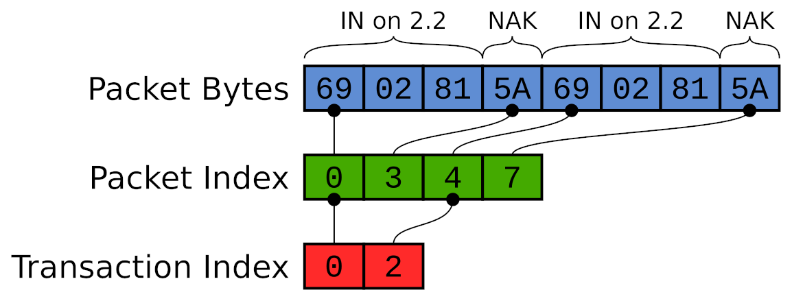
Each index is a monotonically increasing sequence of integers. Because of that, we can store them very efficiently. We use a simple compression scheme to minimize the storage overhead of the indexes. To ensure scalability, these indexes are also streamed to files themselves. As such, capture size is limited only by available storage, never by available memory. All data structures in memory have a bounded size which is independent of the size of the capture.
In this approach, we gain scalability by giving up a little speed at display time. This is a good tradeoff to make, because, unlike capturing or loading data which may happen at extremely high speeds, displaying data is constrained by the bandwidth of the human user. There can only be so many things on screen at once, and the user can only browse through them at human speeds. We do not have to make rendering the display very fast for it to feel instantaneous.
Traffic Display
USB is a highly structured protocol: packets are grouped into transactions, transactions into transfers, and transfers are attached to specific endpoints on devices. Our UI displays traffic hierarchically according to that structure, making captures easy to understand and explore. A similar design approach was pioneered in ViewSB, but in Packetry we’ve now made it fast and scalable to large high-speed captures.
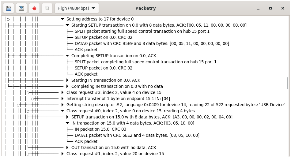
Our GUI has been built on GTK 4, which has built-in support for displaying large lists and trees by lazily loading only the parts currently visible on screen, recycling UI widgets for efficiency, and preloading ahead of scrolling. When you scroll through the traffic view in Packetry, the packets required are loaded on demand using the capture indexes, decoded on the fly, and used to generate the summaries you see of packets, transactions and transfers. All this happens live, too: if you’re running a capture, you’ll see new traffic appear, and the descriptions of existing items may be updated as further packets come in. When you load a capture from a file, you can start exploring it immediately, even while the packets later in the file are still being indexed.
Threading Model
It’s been a while since individual CPU cores got significantly faster; these days performance gains usually come from parallelization to take advantage of multiple cores. However, some tasks just can’t be parallelized, and the only option is to make them as fast as possible on a single thread.
When analyzing packets captured on the wire, every packet matters to the overall state of the protocol. The need to deal with invalid packets and protocol errors means it’s not possible to make assumptions about structure. Interpreting traffic correctly requires looking at every packet one by one, in order, and updating the protocol state at each step. That means our packet decoder has to run as a single thread and be highly optimized for throughput.
We can, however, move everything else out to separate threads so that the core decoder can run as fast as possible. Packetry runs as three threads, each feeding data to the next:
-
The capture thread deals with streaming captured packets from a Cynthion device over USB.
-
The decoder thread processes captured packets, stores them and builds the capture indexes.
-
The UI thread runs the user interface, reading from the indexes and stored packets to display the captured traffic in a human-readable view.
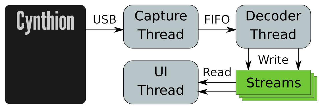
A key feature of the design is that all the interactions between these three threads are lock-free: they cannot block each other. The capture thread supplies packets to the decoder thread through a FIFO queue. The decoder and UI threads use our own lock-free stream implementation, which allows a single writer and any number of reader threads to efficiently share a growing data stream whilst it is being buffered and written out to storage, then mapped back into memory as needed.
Keeping these threads decoupled from each other helps us ensure that capture will always continue to run at a consistent throughput, no matter how complex the the traffic is or what analysis is being done in the UI.
Head to Head
So how fast is it? To give a quick illustration, here’s Packetry and Wireshark loading the same file, side by side. The file is a 300MB capture in pcap format of a HackRF in use.
Packetry finishes loading the file 10x faster — but you don’t even need to wait for that to happen to start exploring the capture. The view is ready to interact with as soon as the first packets are decoded. That happens almost instantly, and you’re up and running immediately with a fully hierarchical, human-readable view of the traffic.
Trying it out
Packetry is still in active development and we don’t have releases or binary downloads yet. If you’re really keen to play with Packetry you can build it from source and try it out with the example capture files that are included in the repository for testing. Build instructions are in the repository.
Renaming LUNA Hardware to Cynthion
Note: This is a crosspost of a Cynthion update on Crowd Supply: https://www.crowdsupply.com/great-scott-gadgets/luna/updates/renaming-luna-hardware-to-cynthion.
Until now, the name LUNA has referred both to our USB multitool hardware platform and to the USB gateware framework that supports it. From now on, we want these projects to have separate names. We’ve decided to name the hardware platform Cynthion. The gateware framework will continue to be called LUNA.
Why are we making this change?
This renaming is happening because we have often had conversations, both internally and with external folks, in which we’ve had to say, “Wait. Are you referring to LUNA hardware or LUNA gateware?” Additionally, we’ve repeatedly fielded questions from folks who have been confused about different features supported by the gateware framework vs. the hardware platform. One common point of confusion in conversation is that LUNA gateware supports SuperSpeed USB while the Cynthion hardware does not. Lastly, projects like ORBTrace and Amalthea use the LUNA gateware framework to drive their projects, but they do not benefit from the association with Cynthion. It would be nice for these projects if they could indicate that they are supported by LUNA gateware without making them seem like add-on boards for Cynthion. Meanwhile, Cynthion is no longer just a development platform for the LUNA gateware, it is its own product and we need a name to refer to just the hardware while in conversation.
What happens next?
In the next few weeks, you can expect to see the hardware design files move from the LUNA repository into a new Cynthion repository we will create in the Great Scott Gadgets organization on GitHub. Following that, you will see the hardware documentation migrate into a folder in the Cynthion repository. Before you receive your hardware, Cynthion, its enclosure, packaging, and marketing materials will be updated to reflect the new name.
All LUNA gateware framework materials will remain as they are in the LUNA repository. There should be no need for existing projects to change how they are interfacing with LUNA.
Why the name Cynthion?
When choosing a name for this hardware platform, we wanted to pick something moon-related like LUNA. As we scrolled lists of moon-related words, “apocynthion” and “pericynthion” stood out to us. We played with subwords like “pericynth” but as a team, we eventually settled on Cynthion. The word Cynthion means “related to the moon” and is derived from Cynthia, an alternative name for Selene, the Greek personification of the moon.
LUNA Revision 0.5 Completed
Note: This is a crosspost of a Cynthion update on Crowd Supply: https://www.crowdsupply.com/great-scott-gadgets/luna/updates/luna-revision-0-5
We are happy to say that hardware revision 0.5 for LUNA has been completed and that revision 0.6 is well under way! Some highlights from revision 0.5 are an upgrade to using KiCAD 6, adding some of our planned part substitutions, and improving labeling. Full details of hardware revision 0.5 can be viewed in the GitHub pull request for that task https://github.com/greatscottgadgets/luna/pull/190. As for hardware revision 0.6, our current set of tasks can be seen in this GitHub issue: https://github.com/greatscottgadgets/luna/issues/185. Progress has been made on almost every item in the r0.6 checklist and we will check the items off as they have been finalized and put through our review process. We look forward to giving you more updates soon!
Updated Delivery Date
Note: This is a crosspost of a Cynthion update on Crowd Supply: https://www.crowdsupply.com/great-scott-gadgets/luna/updates/new-delivery-date
With almost every project, delays tend to happen. LUNA is no different. In good news, we have received all of the components needed for LUNA. In not-so-good news, we have not been as lucky in gathering components for the other products at Great Scott Gadgets. Over the last couple of months, we’ve had to move our head hardware designer (Michael Ossmann) from the LUNA project and onto redesigning some of our other hardware so Great Scott Gadgets can continue to exist through this chip shortage. The result is that we are behind on redesigning LUNA to accommodate the larger FPGA, as discussed in a previous update.
As of now, we have three more hardware revisions we need to complete for LUNA. Revision 0.5, with the original FPGA, has some bug fixes that need to be completed. Then, revision 0.6, with the new FPGA, needs to be started, tested, and finalized. Lastly, revision 1.0, the one we will send out to all of you, needs to be started, tested, and finalized. In the best-case scenario, revision 1.0 will be only a relabeling of revision 0.6. Along with hardware redesigns, we also need to design a slightly bigger case to accommodate the bigger LUNA board and build a test jig that will be used to test the quality of LUNAs built by our manufacturer. We expect these hardware tasks to take three months to complete. Following our hardware work, we will be manufacturing LUNA and shipping it out to you. The manufacturing and shipping processes are expected to take three months.
Altogether, our current delay in getting LUNA to you is another six months. This puts LUNA in your hands in June 2023. We are very sorry about this delay. Every week that we were working on keeping Great Scott Gadgets going, we thought “this is the last week of non-LUNA hardware, we’ll be back to LUNA hardware next week”, but new chip shortages and other roadblocks continued to appear. As soon as those issues were overcome, we reviewed our timeline and wrote you this post. We thank you very much for your patience and continued support as we work to get LUNA into your hands.
Packetry Preview
Note: This is a crosspost of a Cynthion update on Crowd Supply: https://www.crowdsupply.com/great-scott-gadgets/luna/updates/packetry-preview
Due to the delays caused by the chip shortage, there’s not been a lot to report on the LUNA hardware front recently – but behind the scenes, we’ve been hard at work on the software stack which will accompany it. Over the next few weeks, we’ll be making some more updates about that work.
One of LUNA’s key features is its ability to act as a passive sniffer: it can be connected between a computer and the USB devices connected to it, capturing all the traffic between them. This is a powerful capability for debugging, reverse engineering, security research, or just learning how things work.
Up until now, USB capture and analysis with LUNA has primarily used ViewSB, an open source USB-specific application developed here at GSG. ViewSB displays captured traffic as a tree view that follows the structure of the USB protocol: packets are grouped into transactions, which are grouped into transfers. The tree view makes a USB capture easy to understand at a glance. It’s also possible to view LUNA captures with Wireshark, but although that’s a popular and capable tool, Wireshark’s USB dissector provides only a packet-by-packet view of the capture.
As we started to test more and more demanding use cases with LUNA, we began to find that neither tool delivered the performance we wanted to see. Wireshark can take considerable time to load or filter captures with many millions of packets, despite its mature C implementation. ViewSB is written in Python, an interpreted language that generally relies on gluing together native libraries to attain high performance. As we started to deal with larger captures from LUNA, ViewSB’s speed became the bottleneck, and we began to work on moving more of its work into native code.
We started to prototype a new capture and decoding pipeline, focusing on a new data structure design that would be fast to both construct and access, and that would scale to large captures. Initially we worked in C, with some UI code in Python, and intended on integrating this work into ViewSB.
Another issue we wanted to address was the ordering of items in the view. When multiple transfers happen simultaneously, a conventional tree view can become confusing or misleading, as the tree structure may not match the chronological order of events. Fixing this needed deeper changes, especially when combined with the need for efficient handling of large captures.
As development on both issues progressed, we came to the conclusion that we could make quicker progress, and achieve a better end result, if we directed our efforts into a new application written in Rust. That project is now approaching readiness for its initial release, and we’ve named it Packetry.
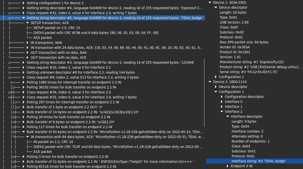
Packetry isn’t just ViewSB rewritten in Rust; the underlying design is fundamentally different, and it has been redesigned from the ground up. Our goals when developing Packetry were:
-
To provide the best possible end user experience for USB analysis with LUNA.
-
To handle large captures effortlessly, with minimal loading time and instant UI response, regardless of capture size or complexity.
-
To present a new visualization approach: one that maintains the hierarchical advantages of a tree view whilst keeping timing relationships visible.
As with everything we develop, Packetry is open source, and you can follow the work in progress on GitHub. Over the next few weeks, we’ll be merging in the various feature branches we’ve been working on as we get ready for the initial release. As we go along, we’ll make some further updates here on Crowd Supply, explaining the new design in more detail.
FPGA Substitution on LUNA
Note: This is a crosspost of a Cynthion update on Crowd Supply: https://www.crowdsupply.com/great-scott-gadgets/luna/updates/fpga-substitution
Global supply chain issues continue to be difficult to traverse, but once in a while we do get a little bit lucky! In a previous update [1] we mentioned that Lattice had pushed out the lead time on our FPGAs for LUNA from 30 weeks to 60 weeks. Well, the expected delivery date for those FPGAs got pushed out again. Thankfully, we were able to purchase another ECP5 part for the first batch of LUNAs from an authorized Lattice distributor in a 381-ball package rather than a 256-ball package. We already have the 381-ball FPGAs in hand, so we don’t have to worry about those lead times changing again. We are still waiting on other components though, so with this FPGA substitution our estimated shipping date for LUNA will still be December 2022.
Changes to LUNA
Both FPGAs are from the same manufacturer and are part of the same line. The firmware and software we are creating will work the same regardless of which of the FPGAs is present on a given LUNA board. The primary difference impacting LUNA is that the substitute FPGA is slightly bigger than the original FPGA we had picked out. The original FPGA was 14x14 mm and the substitute FPGA is 17x17 mm. To accommodate this change in size we expect to increase the board area of LUNA to 51x51 mm instead of its original 48x48 mm.
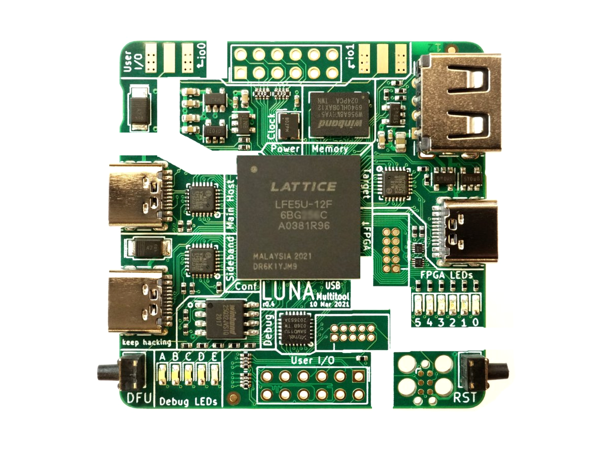
This change adds 297 millimetres squared of available space. 93 millimetres squared of the extra space will be taken up by the bigger FPGA which leaves 204 millimeteres squared to use. The Great Scott Gadgets team has not yet settled on what we will be doing with the extra space but we will update you all as soon as we finalize our decisions. If you would like to make requests for or share your thoughts on what to use this space for, please come discuss in our Discord server.
[1] https://www.crowdsupply.com/great-scott-gadgets/luna/updates/luna-delayed
HyperRAM controller for USB analysis
Note: This is a crosspost of a Cynthion update on Crowd Supply: https://www.crowdsupply.com/great-scott-gadgets/luna/updates/hyperram-controller-for-usb-analysis.
One of LUNA’s core features is the ability to perform protcol analysis of USB 2.0 low-speed, full-speed, and high-speed. For most target devices, LUNA can endlessly stream the capture directly to a host PC over its own high-speed port. However, for high-bandwidth target devices that can’t be streamed in real-time, LUNA has 8 MiB of memory on board to buffer captured data before sending it upstream.
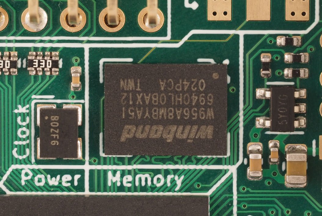
On LUNA we’re using HyperRAM, a type of pseudo-static RAM, which is capable of achieving relatively high speeds while being much simpler to work with than DRAM as it handles refreshing of the memory array by itself. Recently we’ve been working on our Amaranth gateware that interfaces with the RAM, implementing support for memory-space reads/writes and speeding it up so that we can keep up with USB analysis.
Speed
For USB analysis, we need to be able to stream data through the RAM at a nominal 480 Mbit/s but, since the ram is half-duplex, we need to hit at least double that. We also need to allow for some overhead for the RAM protocol. In our controller we run the RAM at 120 MHz DDR for a nominal rate of 1920 Mbit/s, which gives us plenty of margin to keep up with high-speed USB.
The Lattice ECP5 FPGA used on LUNA has a nifty feature in the I/O cells called gearing, which serializes/deserializes data to allow the I/O pin to run at a high speed without requiring the FPGA fabric to match it. For our HyperRAM controller we use the IDDRX1 and ODDRX1 cells, which take a 2-bit signal and read from/write to I/O pin at double the speed.
Timing challenges
A challenging part of interfacing with HyperRAM is the wide range of data-valid timing. The datasheet specifies that the data lines can be valid anywhere between 1 ns and 7 ns after a clock transition, and become invalid anywhere betwen 0.5 ns and 5.5 ns after the next clock transition. Running at 120 MHz the time between clock edges is only 4 ns, so this means that there is no fixed window in which to sample! The diagram below shows some examples of how the data-valid window could be shifted relative to the clock:
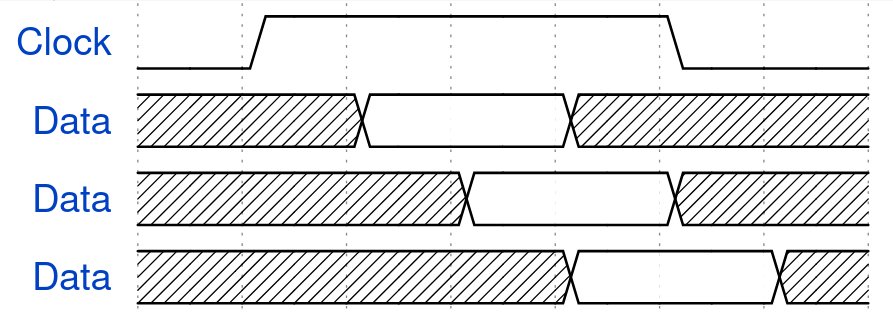
We solve this by using the ECP5’s I/O delays to shift the data-valid window and align it with a clock edge. These delays are variable so we can adjust them during operation to find the range of values that result in successful memory reads, then pick the value in the middle for the ideal sampling point.
Debug tooling
For projects like this, it’s important to have good tools for debugging! As part of this work we wrote a HyperRAM decoder for glscopeclient, an open source frontend for oscilloscopes. This makes it easy to interpret waveform captures from the real hardware, and verify that everything is working as expected. The decoder has been merged upstream, so it’ll be available with any recent glscopeclient install.
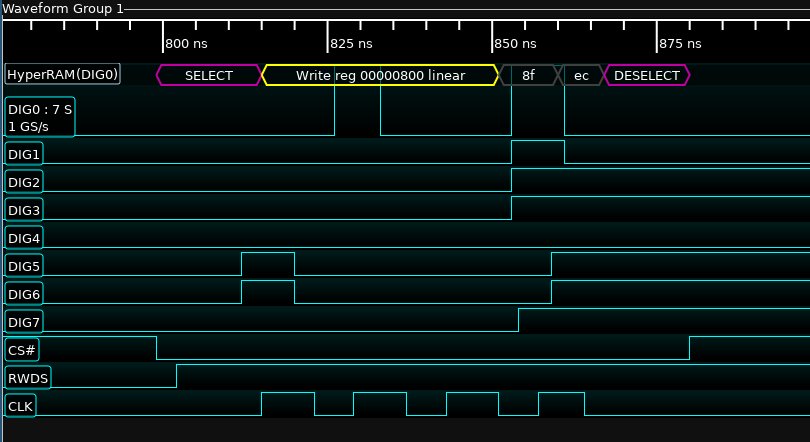
LUNA Now Uses Amaranth HDL
Note: This is a crosspost of a Cynthion update on Crowd Supply: https://www.crowdsupply.com/great-scott-gadgets/luna/updates/luna-now-uses-amaranth-hdl
Over the next while we will be updating the LUNA project to use “Amaranth HDL”, which is the new name whitequark and other maintainers have chosen for their project. Amaranth is the hardware description language used in LUNA. The Amaranth gateware provided with LUNA enables you to create USB devices in gateware, firmware or both. Amaranth also enables LUNA to customize itself to the task at hand, which gives it access to unique features like user-defined hardware triggering and simultaneous capture of additional external or internal signals. The GitHub location for the Amaranth HDL project is https://github.com/amaranth-lang/ and if you want to talk with other Amaranth users you can join the #amaranth-lang IRC channel on http://libera.chat.
LUNA Delayed
Note: This is a crosspost of a Cynthion update on Crowd Supply: https://www.crowdsupply.com/great-scott-gadgets/luna/updates/luna-delayed
LUNA is delayed. All of us at Great Scott Gadgets are sad to have to give this news, but the global chip shortage and supply chain chaos has impacted our LUNA manufacturing and delivery timeline more deeply than anticipated. Unfortunately, LUNA is now expected to start shipping December 2022 because the lead time for the ECP5 FPGA chip we use on LUNA doubled between July and September. There isn’t a suitable substitute component for the ECP5, so our timeline depends on Lattice’s production schedule for this chip. Please know that getting LUNA into your hands as soon as possible is our highest priority, and has been since before the Crowd Supply campaign was launched.
During our Crowd Supply campaign planning, we did a lot of prep work to make sure we had the most accurate estimate of LUNA time to delivery possible. Our planning involved getting seven quotes and lead times from four different contract manufacturers in the time leading up to the campaign. One of these manufacturers stood out to us and we have now requested quotes and lead times from them twice. We received the first quote from this manufacturer on July 10th, which was prior to the campaign, and the second on September 17th, which was just after we got the the funds from the campaign.
The July 10th quote indicated that the microcontroller (ATSAMD11) on LUNA would be the component with the longest lead time at approximately 52 weeks. This was unsatisfactory as we did not want to wait over a year to get LUNA to you. We started looking for substitutions and alternative component sourcing methods immediately. We found an alternative source for the ATSAMD11 very quickly but did not know how many to order since our crowdfunding campaign hadn’t ended and we didn’t yet have the funds to order components. The day the campaign ended we put our order in for the microcontroller. We are happy to say that we received these components at the end of September! Our next step is to ship these parts from our office to our manufacturer.
The component with the next longest lead time on the July 10th quote was the ECP5, which is the main FPGA on LUNA. Our manufacturer gave us a 30-week lead time on this component in that quote, which is what we based our LUNA timeline on. When we got the September 17th quote, the lead time jumped from 30 weeks to 60 weeks. The ECP5 is now the LUNA part with the longest lead time. Until recently, the longest we typically have had to wait on any one part for a Great Scott Gadgets product was 16-20 weeks so many of these lead times are outside of our usual expectations.
Since receiving the bad news about the ECP5 lead time, we have made efforts to reduce the time to delivery. First, we attempted to shorten the ECP5 lead time by contacting Lattice directly to see if they could work with our manufacturer to supply ECP5s for LUNA. This attempt led to a dead-end and did not improve our timeline. Next, we worked with our manufacturer to source the ECP5s from another parts distributor; we had some success there as the manufacturer was able to find another source of ECP5s with a 50-week lead time. We have asked them to put an order in for these ECP5s. At the same time we found another parts distributor that was able to sell us ECP5s quoted 36 weeks, and we ordered them immediately. The next day we received an email from the distributor of the second round of ECP5s we ordered and they updated their lead time from 36 weeks to “to be determined”. Neither of these ECP5 orders are cancellable so we’ve invested heavily in getting LUNA to you as soon as we can. We hope that one order or the other will come in sooner than the 50-week lead time. We will keep you updated!
While we are disappointed that we’ve had to revise our estimated ship date to account for the component delays caused by the global chip shortage, we do have some good news. The delay gives our small team even more time to hone the LUNA software and experience before getting it into your hands. We will use this time to collect and address more feedback from our beta testers, create extra demos and training material, and continually improve our documentation.
If you have any questions, thoughts, or suggestions please reach out to the Great Scott Gadgets team through GitHub or Discord at any time. We would especially welcome any leads about ECP5s!
Pmod Host Ports Added to Encased LUNAs
Note: This is a crosspost of a Cynthion update on Crowd Supply: https://www.crowdsupply.com/great-scott-gadgets/luna/updates/pmod-host-ports-added-to-encased-lunas
In one of our updates on CrowdSupply we asked you all for feedback about whether populating the optional Pmod host ports would be a welcome addition to LUNA, and whether they should be added to bare board LUNAs, encased LUNAs, or both. We got many comments through our Discord, direct messages, email, and GitHub. The feedback was overwhelmingly in favour of adding Pmod host ports to encased LUNAs only, so we are going ahead with that change!
LUNA General-Purpose Digital I/O
Our main goal in adding the Pmod host ports/footprints to LUNA was to add general-purpose digital I/O functionality to the board. This functionality can be used, probably most importantly, as trigger inputs or outputs that are synchronous with USB operations on LUNA or a device connected to LUNA. We’ve already used this I/O ourselves to test a circuit option that is now included in the latest LUNA design! Mike Walters has also used the Pmod host ports to stream data from a proprietary thermal camera interface.
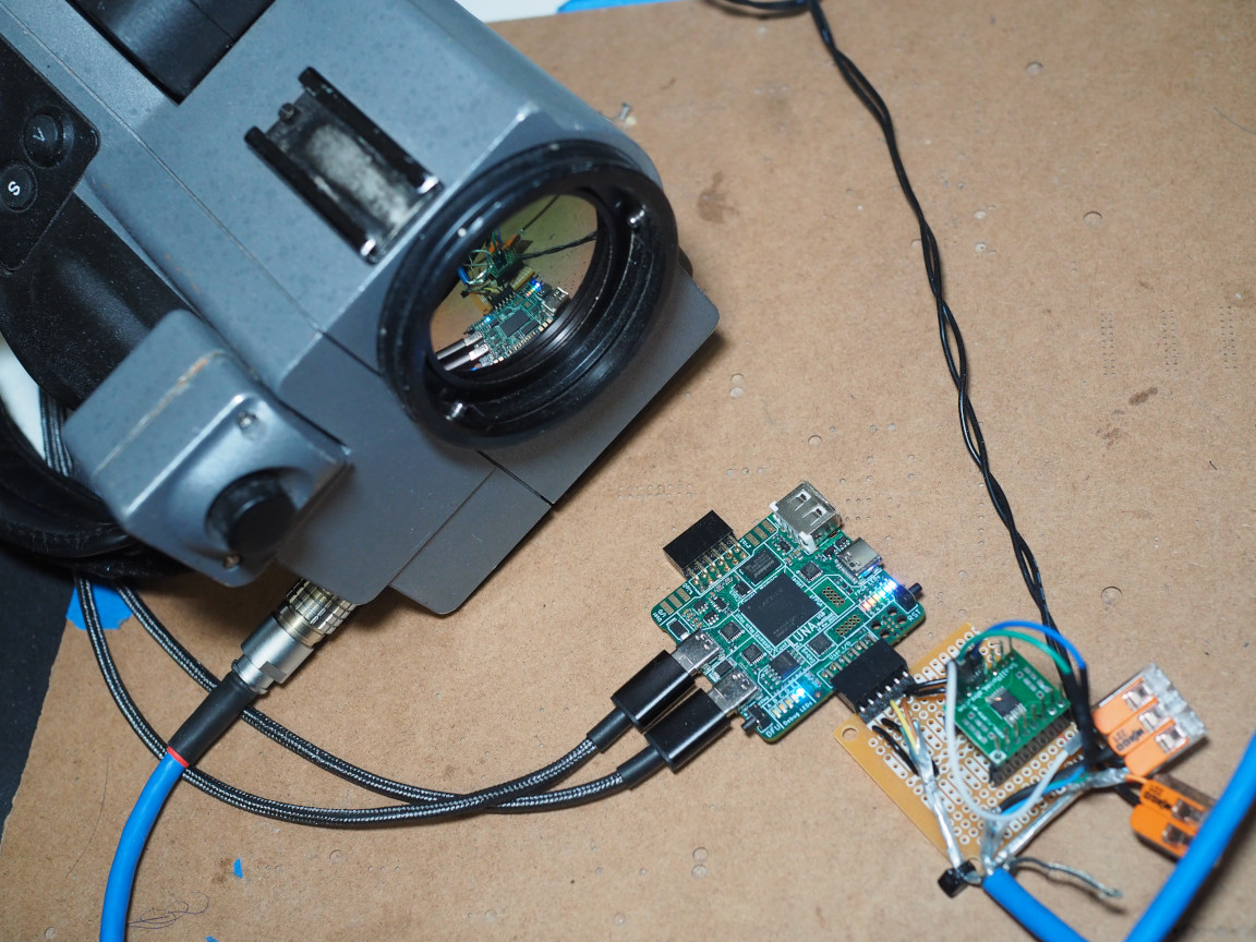
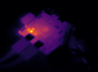
Pmods and Pmod Host Ports
Pmod stands for “Peripheral Modules”. Pmods are external boards that can be plugged into Pmod host ports on a host board to add functionality to a microcontroller or, in LUNA’s case, an FPGA on that board.
“This functionality includes audio amplifiers, GPS receivers, USB to UART interface, seven-segment displays, accelerometers, H-bridges with input feedback, analog-to-digital converters, and much more” [1]. Pmod host ports are made of 6-pin sections where one pin is for power, another is for ground, and the last four provide digital I/O [2]. These 6-pin sections can be used for plugging in Pmods, or they can be used as needed for general-purpose digital I/O. Digilent has blog posts and videos that dive into Pmods a lot further if you want to learn more.
LUNA and Pmods
While LUNA’s Pmod host ports are intended to be compatible with Digilent’s specification for Pmods [2], we do not have plans to provide dedicated software support for any particular peripherals. Fortunately, the flexibility of the LUNA framework and nMigen enables you to write your own I/O functions for Pmods that you’d like to use with LUNA. Tom Keddie has already provided an example of this [3]. We suspect that the Pmod host ports will likely be most useful to USB device developers, testers, and security researchers.
Physical changes to LUNA and case
The only visible difference to encased LUNAs will be a 12-pin Pmod host port face on either end of the case. If removed from the case, each Pmod host port will extend 8mm out from either end of the previously encased LUNA. This will make previously encased LUNAs 16mm longer than bare board LUNAs that don’t have the Pmod host ports populated. The Pmod host ports will only extend 5mm above the board, which is not as high as the USB Type-A connector already present.
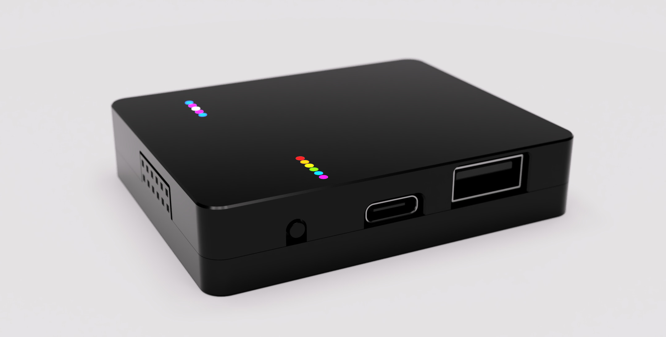
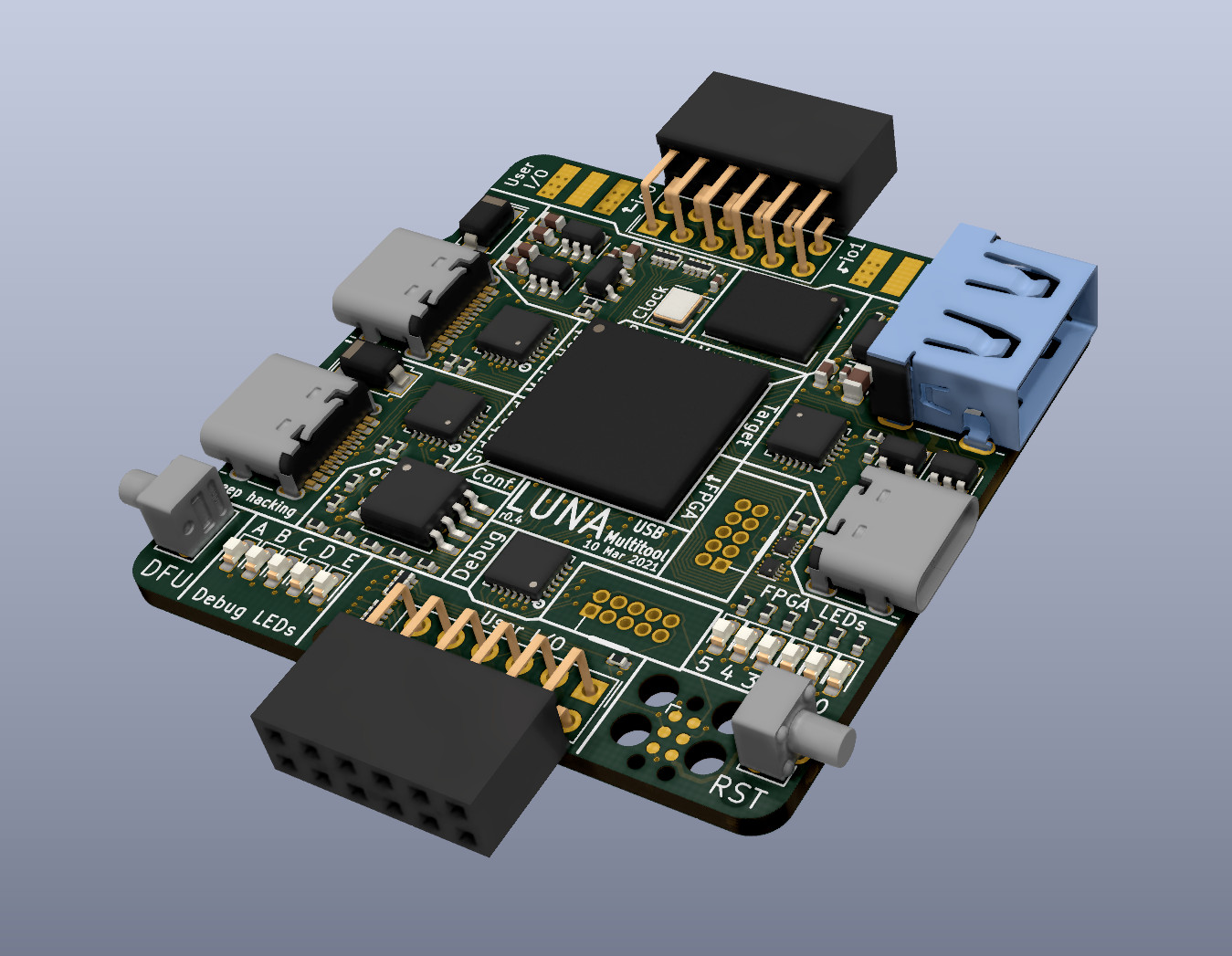
Pmod footprints will remain on bare board LUNAs so Pmod host ports can be soldered on later by those that wish to have them.
References
[0] https://digilent.com/blog/where-to-plug-in-your-pmod-fpga/
[1] https://digilent.com/blog/digilent-pmods-an-introduction/
[2] https://www.digikey.ca/htmldatasheets/production/2033310/0/0/1/pmod-interface-specification.html
Second LUNA Enclosure Update
Note: This is a crosspost of a Cynthion update on Crowd Supply: https://www.crowdsupply.com/great-scott-gadgets/luna/updates/enclosure-details-and-contest-winner
Enclosure Update
We have an update on the enclosures! We have received 10 enclosures from our manufacturer and we are impressed.
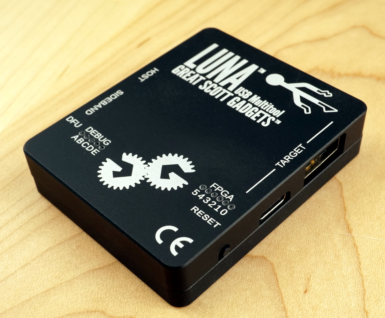
A LUNA in a case measures 2 inches by 2.5 inches and weighs 103 g with the hardware and lightpipes installed. I’ve been carrying mine around constantly like a pet rock since it has such a comfortable weight. The case has held up really well, regardless of the wine, pesto, sesame oil, and other sauces I’ve gotten on it while cooking. The USB-C ports have a satisfying amount of hold which means that any cables won’t get knocked out easily.
Enclosure Modifications (?)
The members of the Great Scott Gadgets Discord did get a preview of the LUNA enclosure a couple weeks ago and have already given us some feedback, which we greatly appreciate. If you have any opinions on the suggestions made, or have suggestions of your own, we’d love to hear them. We make our devices for you all and this is your chance to bring up any enclosure design or usability concerns before we start production.
One enclosure design choice that is currently being debated is whether we should populate the Pmod connectors on LUNA, shown on the left edge of the enclosure in the picture below.

In the case, the Pmod connectors don’t change the form factor, but on the bareboard LUNA the Pmod connectors would extend 5 mm above the board (which is not as high as the USB Type-A connector), but they would each add 8 mm of length to the board.

Please let us know whether you would like to see LUNA come with Pmod headers pre-installed on both LUNA in a case and bareboard LUNA, one or the other, or neither by voting with emoji on the relevant question posted in the feedback channel in our Discord server.
Case Contest Winner
To wrap up this post on the LUNA case design, we are happy to congratulate Rémy on winning the case contest with their design. Rémy will receive the only LUNA case with his winning design etched in the case:

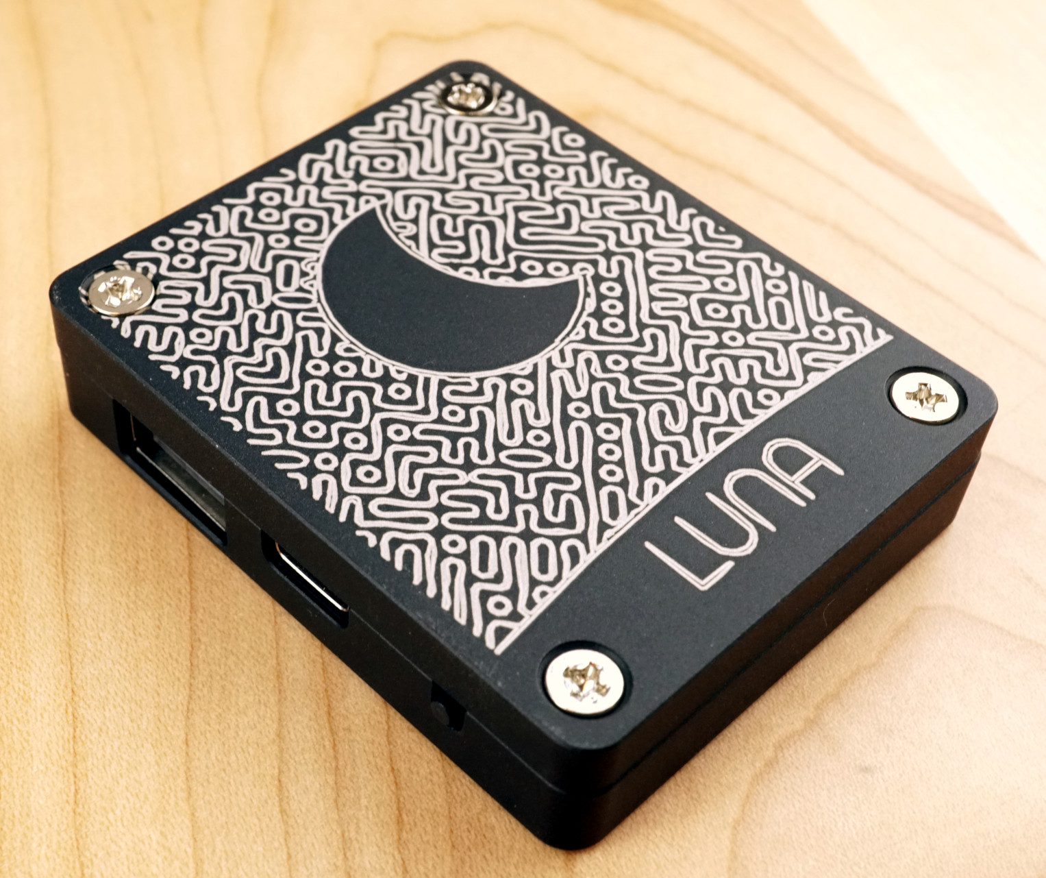
AMA on CrowdSupply
Note: This is a crosspost of a Cynthion update on Crowd Supply: https://www.crowdsupply.com/great-scott-gadgets/luna/updates/ama-update
On August 18th we held an “Ask Me Anything” session where anyone interested in LUNA could ask us questions in real time. The full transcript of this AMA is available to view in the #luna-ama channel in the CrowdSupply Discord server.
The History of LUNA
Note: This is a crosspost of a Cynthion update on Crowd Supply: https://www.crowdsupply.com/great-scott-gadgets/luna/updates/the-history-of-luna
Starting Great Scott Gadgets
Ten years ago this summer I quit my day job at a radio research lab and made Great Scott Gadgets (GSG) my full-time job. I dedicated myself and the company to our mission: to put open source tools into the hands of innovative people. One of the first things I did at that time was to make a list of products I was interested in making. That list included “USB swiss army knife”. I didn’t know how to make such a thing at the time, but it was something I had in mind from the start. I soon started referring to the concept as “usbstar” in my private notes and envisioned that it would be shaped something like a three-pointed version of the Throwing Star LAN Tap. I wanted it to have three points with one USB port each for implementing Meddler-in-the-Middle (MitM) or active monitoring. One port would be connected to a target host, another to a target device, and the last to the monitor/control host.
A year later I hired Dominic Spill. Around that time Travis Goodspeed released his Facedancer software along with hardware based on his GoodFET project. Facedancer was exciting because it allowed rapid development of USB devices in Python, making it highly useful for security testing of USB hosts.
In 2013, Travis, Dominic, and I had a chat in a pub where we discussed ideas for next-generation Facedancer hardware similar to the usbstar concept. We thought that we could make a microcontroller-based platform similar to GoodFET with two or three USB 2.0 ports that would be faster and more capable than the target USB port on Facedancer. In that conversation, one of us (Dominic, I think) first proposed the name “GreatFET” for a Great Scott Gadgets variant of GoodFET, although we imagined at that time that GreatFET and Facedancer would be two different hardware platforms.
Daisho
After releasing HackRF One, we had expanded the usbstar idea into a greater vision that became Daisho. This project had an FPGA-based mainboard with pluggable modules, each for a different high speed communication technology: one for SuperSpeed USB 3.0, one for Gigabit Ethernet, and one for HDMI. It was a big project, but, thanks to some outside funding, we were able to hire help.
With Daisho we implemented SuperSpeed USB MitM capability, demonstrated by Jared Boone who designed both the mainboard and the USB module. It was only just working in time for the demonstration, but it was an effective proof-of-concept of FPGA-based USB MitM.
When our funding for Daisho ran out, however, we realized that we had created a good tool for our research but hadn’t created a viable product. We felt that Daisho was too big and expensive to have much hope of commercial success in our community. It was an overly ambitious project, but we learned a lot in the process.
One nice thing that came out of the project was the Daisho USB 3.0 device core developed by Marshall Hecht. This was the world’s first open source USB device core for FPGAs, and it has since been ported to other platforms and used in actual products.
Around the end of the Daisho project, Dominic visited the GSG lab in Colorado for some project planning. In a brainstorming session, he, Taylor Streetman, and I sketched out a usbstar design together: It had an FPGA in the middle, surrounded by three USB 2.0 PHY chips. The idea was to take what we had learned from Daisho but to scale its USB capabilities down to a single board that was simpler and more affordable.
We wanted to start working on it immediately, so I ordered an FPGA development kit to arrive during Dominic’s visit. By the time the kit arrived, however, we had talked ourselves out of the project!
One reason we didn’t pursue the usbstar concept at that time was that neither of us had very much FPGA experience. Without external funding to hire folks like those who had helped us with Daisho, we felt our progress would be slow. We also weren’t excited about building an open source product that relied on proprietary (and in some cases expensive) FPGA development tools. We liked the idea, but we prioritized GreatFET instead.
GreatFET
Another reason we abandoned usbstar was that we had expanded our vision for GreatFET. Instead of the minimal microcontroller I had used in my initial prototype, we chose the LPC43xx series that we had used in HackRF One. With this part we were able to place two USB interfaces on GreatFET One with potential for a third USB port on an add-on board (called “neighbors” in honor of Travis). By making GreatFET “greater” in this way, we tried to enable the most important capabilities of the usbstar concept without having to additionally pursue the FPGA-based project. While GoodFET and the original Facedancer hardware were two different platforms, GreatFET combined those functions into a single board.
While we were developing GreatFET, Dominic started collaborating with Kate Temkin on some USB projects. Kate single-handedly ported/rewrote Travis’s Facedancer software for GreatFET One and other platforms, and the two of them worked on GlitchKit and USBProxy. We hired her as a contractor to develop USB training courseware and GreatFET software, and she eventually joined us as a GSG employee.
Not long after joining the GSG team, Kate started developing Rhododendron, a GreatFET neighbor for High-speed USB analysis. Rhododendron was designed to be the simplest, lowest cost circuit for passive monitoring of High-speed USB. Kate and Mikaela Szekely demonstrated Rhododendron at Teardown 2019 along with ViewSB, their new USB analysis software.
LUNA Hardware
In the months following that demonstration, we worked toward manufacturing Rhododendron, but Kate started questioning whether or not it was really the best approach. Rhododendron was designed to be ultra-low-cost, but it additionally required purchase of a GreatFET One. She began thinking about making a much more sophisticated and capable tool in the same price range as the combined cost of GreatFET One and Rhododendron.
We didn’t see Kate at the lab for a couple weeks late in 2019, and then one day she appeared and announced that she had designed a new USB multitool. LUNA was born! She showed us the design, and I immediately recognized the FPGA-based usbstar concept that Dominic and I had sketched several years prior. Design work we thought would have taken us months Kate had accomplished in two weeks! Additionally she had included a fourth pass-through port for passive monitoring, making LUNA a hybrid of usbstar and Rhododendron.
One of the exciting aspects of Kate’s initial design was that LUNA was based on the ECP5 FPGA which had only recently become supported by an open source toolchain thanks to gatecat and other members of the open source FPGA community. We felt that, with the availability of open source tools, the time was finally right for GSG to make an FPGA-based design. The ECP5 was a perfect choice for LUNA as it has the performance necessary for multiple High-speed USB interfaces at a low cost.
Another thing that excited us about LUNA was Kate’s vision for gateware based on whitequark‘s nMigen, combining the flexibility and power of FPGAs with the rapid development of Python.
The Impact of COVID-19
Sadly, at about this same time the SARS-CoV-2 virus that causes COVID-19 first infected humans. We didn’t know about it until January of 2020 when it quickly became a major concern for us at GSG. We learned on the 24th of January that due to the lockdown in China we had lost access to a warehouse containing thousands of our products, the first of several pandemic-related supply chain problems that have affected us over the past year and a half.
Although we suffered a dramatic loss of revenue in the first quarter of 2020, we were able to continue paying our staff thanks to pandemic relief loans from the US government. Applying for loans was a stressful and lengthy process due to high demand and to the government and our bank having to rapidly develop new policies and procedures. We took on debt, some of which has been forgiven, but we felt that it was worth it to continue supporting our team of eight through the pandemic.
We began requiring remote work in early March. With everyone working at home and with supply chain issues limiting our hardware sales, we made LUNA development our top priority. We felt that investing in our team was the best use of pandemic relief funds and that LUNA was the best focus for the team’s efforts.
Team and Community Contributions
Kate focused on the all-important gateware and software development. She wrote code to quickly bring up her initial prototypes and validate basic functions, and she has since built the framework to support more advanced LUNA capabilities.
I took over as hardware designer after Kate’s r0.2 design. My work was made easier by the fact that Kate’s initial two designs were (incredibly!) fully functional almost without modification. Over the last year I still found enough things to refine that I ended up rerouting every trace on the PCB.
Mike Walters contributed to LUNA by developing hardware and gateware for Amalthea, an experimental Software-Defined Radio platform based on LUNA. This is important work because we see LUNA not just as a USB multitool but also as the basis for diverse future USB-connected GSG projects.
Mikaela worked on ViewSB and Facedancer software, providing the user-facing tools that will allow folks to do powerful things with LUNA.
Taylor focused on mechanical aspects of the design, such as creating a prototype enclosure. He also coordinated with contract manufacturers and component suppliers to ensure manufacturability at our target price.
Elizabeth Hendrex planned this Crowd Supply campaign while maintaining business operations and keeping everyone employed throughout the pandemic.
Straithe took the lead on technical support and documentation for all GSG products and projects, including LUNA. She also assumed responsibility for community communication such as these updates, Twitter, and Discord.
We engaged Timon Skerutsch to design the milled aluminum enclosure and help us with sourcing.
Meanwhile several members of our open source community contributed code to LUNA and related projects, and we launched this campaign as a way for the community to ensure that we will be able to put LUNA into the hands of innovative people. It has been wonderful to witness the team and the community come together to make LUNA a reality!
Thank You
With this campaign we’ve begun a new chapter in LUNA’s history. Kate and Mikaela have recently resigned from their roles at GSG and will no longer be a part of the project. We thank them for the outstanding work they’ve done to make LUNA what it is today, and we look forward to continuing our team effort to bring LUNA’s exciting capabilities to the community. Thank you all so much for your support. We couldn’t do this without you!
Open Source Clair de Lune
Note: This is a crosspost of a Cynthion update on Crowd Supply: https://www.crowdsupply.com/great-scott-gadgets/luna/updates/open-source-moon-music
Open source is at the heart of everything Great Scott Gadgets does. When we design hardware, we publish the KiCad design files, firmware, and software under open source licenses. We try to ensure the documentation, tutorials, research papers, and videos we publish are openly licensed as well. It is the GSG way. While preparing for this Crowd Supply campaign, we took our commitment to open source even further by ensuring the music used in our campaign video is openly available too.
As we started thinking about our campaign video, we began to wonder what music we should use. While electronica is a traditional choice, I thought we might consider a more diverse set of options, including classical or acoustic music. I started my search by investigating music inspired by the moon.
I looked through a list of moon songs for ideas but decided it would be too much of a hassle to get rights for a popular song. Then I looked at a classical list and realized I had sheet music for some of the pieces. I sat down at my piano and tried to play a few. Straithe was listening, and when I started playing Debussy’s Clair de Lune she immediately said, “Use that one.”
Shortly thereafter, I suggested Clair de Lune in a planning meeting with Elizabeth and Kate. They both thought the idea had some merit, but neither was excited about it. Elizabeth ended the debate by volunteering to take on the challenge of editing the video and making the final music selection.
A few weeks later, Elizabeth shared a draft video with us, and I was pleasantly surprised she had used Clair de Lune for the music! She said she had investigated a number of other options but kept coming back to Debussy. Although she didn’t favor Clair de Lune for the video at first, it was a piece of music she had always loved. The idea of accompanying LUNA with beautiful music inspired by moonlight grew on her. Unfortunately, we didn’t have rights to use the recording in that draft. We looked around for royalty-free options but couldn’t find any we liked.
At this point we briefly entertained the option of making our own recording. At least three of us in the company were theoretically capable of doing so, but it would have taken a lot of work. Practicing, tuning a piano, acquiring recording equipment, and setting it up would have required several days of effort before even starting the actual recording and editing. We felt it was more important to spend our time focused on LUNA development and preparation for production.
Then it occurred to me: We could hire my brother, David O. He’s a professional musician who could probably record the entire piece in one day. Normally most of his work is in musical theater, but during the pandemic musical theater hasn’t been a thing. Small gigs like this are more important to him now than they have been in the past, and we liked that our project would help support an artist. Additionally we realized we could pay him to release the recording for others to use! Great Scott Gadgets is not in the music business, but, as long as we were producing music, we wanted to do so in the most GSG way possible.
David considered recording with an acoustic piano but decided to use a digital keyboard instead. This process allowed him to edit nuances of his performance such as the timing or velocity of a single keypress and to share his work as a MIDI file. This appealed to the Great Scott Gadgets team as it is in the spirit of the Open Source Hardware Definition which requires design files to be published “in the preferred format for making changes”.
Please enjoy and use his recording, a portion of which is used in our video. In addition to the audio track, he has released the MIDI file that can be edited in sequencing software. When you listen, imagine the beautiful light of the moon or of the LEDs on LUNA!
LUNA's USB-C Connectors
Note: This is a crosspost of a Cynthion update on Crowd Supply: https://www.crowdsupply.com/great-scott-gadgets/cynthion/updates/q-and-a-session-on-luna-hardware-connectivity
Hi, friends!
As community manager for Great Scott Gadgets, one of my favourite tasks is finding answers to questions that come in through email, Twitter, GitHub, and Discord. Thankfully you all are great at asking questions, especially about the USB Type-C connectors on LUNA! In this blog post Michael Ossmann responds to most of the USB Type-C queries I’ve received (and asked) about LUNA in the last few weeks.
Community Question: Old pictures of LUNA feature Micro-USB connectors but the latest pictures show USB Type-C connectors. Why the change?
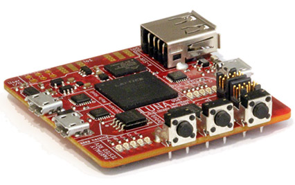
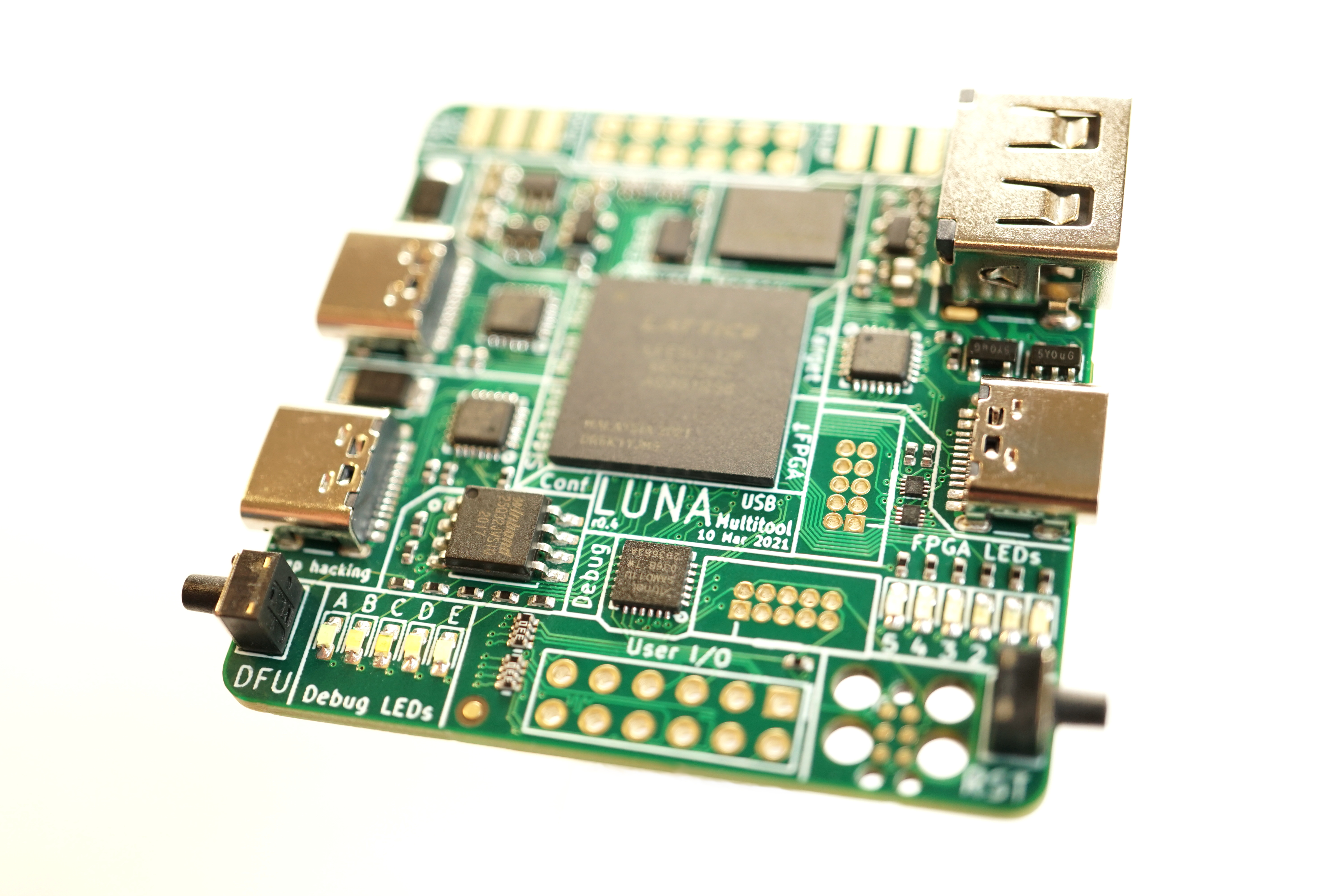
Kate’s original LUNA design used Micro-USB connectors, but we decided to switch to Type-C connectors a couple of revisions later. Based on the USB specification, Micro connectors may be the best choice for LUNA, but I don’t know anyone who actually likes them. They can be difficult to insert properly and they are less reliable than other USB connectors. Maybe the best thing about them is that the cable that tends to wear out and not the receptacle.
Straithe Question: So other than likeability, are there other reasons USB Type-C connectors were chosen?
Type-C connectors are more robust and easier to insert than Micro-USB, particularly since they function when inserted in either orientation. They have become quite common, so we think folks are likely to already have cables. Significantly, Type-C is the only connector specified for the recent USB 3.2 and USB4 standards, so we see it as the most future-proof option in regards to cable acquisition.
Straithe Question: Were there any concerns about switching to USB Type-C connectors?
Our biggest concern about switching to Type-C connectors was that it might give a false impression that LUNA supports SuperSpeed USB, often referred to as USB 3.0. We’ve noticed more and more USB 2.0 devices with Type-C connectors over the past couple years, so our hope is that few people would be confused by this.
Type-C connectors also cost more than Micro connectors, which was an important consideration for us since there are three of them on LUNA. One of the ways we have tried to make LUNA accessible is by making it affordable. Fortunately, we were able to find USB 2.0 Type-C connectors that cost less than USB 3.0 Type-C connectors that include SuperSpeed signals.
Community Question: Will LUNA be able to support SuperSpeed with software changes?
No. A Type-C connector can be used on a USB 3.0 device for SuperSpeed, but it can also be used on a USB 2.0 device such as LUNA at Low-speed, Full-speed, or High-speed. Although the LUNA software framework includes some experimental support for SuperSpeed USB on alternative hardware platforms, the LUNA hardware platform is a low-cost device supporting only USB 2.0 speeds.
Straithe Question: You’ve mentioned a number of different USB speeds. To recap, what are the different USB speeds and what USB versions do they line up to?
There are four speeds in the USB 2.0 and USB 3.0 specifications:
| Speed | Data Rate | First Appearance |
|---|---|---|
| Low-speed | 1.5 Mbps | USB 1.0 |
| Full-speed | 12 Mbps | USB 1.0 |
| High-speed | 480 Mbps | USB 2.0 |
| SuperSpeed | 5000 Mbps | USB 3.0 |
(Additionally there are extensions of SuperSpeed in USB 3.1 and above.)
Although the USB 2.0 specification updates previous specifications and includes both Low-speed and Full-speed, a lot of folks refer to High-speed USB as “USB 2.0”. Similarly, people often refer to SuperSpeed USB as “USB 3.0”, even though it can be found in various versions of the specification higher than 3.0. The USB 3.0 specification supplements USB 2.0, adding SuperSpeed signals on additional wires while following the USB 2.0 specification on other wires within the same cable.
Community Question: Does LUNA come with any cables?
Partly because of our switch to Type-C connectors and partly to save cost and packaging, we have decided not to include cables with LUNA. One of the reasons for this is that it is difficult to predict what cables folks will need for different applications. As an illustration, I used LUNA recently in-line on a connection between a PC and a HackRF One. This required four cables:
- A-to-C cable between the PC and LUNA’s Target C port
- A-to-Micro between LUNA’s Target A port and the HackRF One
- C-to-C cable between my laptop and LUNA’s Host port
- A-to-C cable between my laptop and LUNA’s Sideband port for programming
This particular selection of cables depended on the available ports on the laptop, the PC, and the HackRF One. In order to accommodate most of the combinations we anticipate, we would have to include at least half a dozen different cables, making LUNA needlessly expensive and its packaging overly bulky. Instead we decided to keep LUNA small and affordable by relying on LUNA users to acquire their own cables for their individual needs.
Community Question: Does LUNA pass through SuperSpeed signals when used as a USB analyzer?
To use LUNA as a USB analyzer, you use one cable to connect a USB host to LUNA’s “Target” Type-C port and another cable to connect a USB device to LUNA’s “Target” Type-A port. Both of those ports on LUNA are USB 2.0 connectors, so they only pass through the USB 2.0 data signals. LUNA does not pass through SuperSpeed signals or any of the ancillary signals supported on some Type-C devices such as those used for Power Delivery (PD) communication.
Community Question: I guess LUNA doesn’t have any PD capabilities then?
Although we don’t pass Power Delivery signals through LUNA, the hardware is designed to have some ability to transmit and receive PD signals:
| Port | PD Transmit | PD Receive |
|---|---|---|
| Target A | no | no |
| Target C | yes | yes |
| Host | no | yes |
| Sideband | no | yes |
We added these capabilities to the hardware design when switching to Type-C connectors, but we currently do not have a plan to implement gateware for PD. If you have a specific use case for which you would like software support, please let us know. At a minimum it will be possible to implement your own PD solution in nMigen. Note that LUNA’s Type-C ports are not tolerant of voltages above USB’s standard 5 V, so some PD experiments could put your LUNA in danger of overvoltage.
For more sophisticated PD testing and experimentation, including passive monitoring, I recommend checking out Rod Whitby’s USB-PD Add-On for Glasgow currently in development. Rather than adding similar circuitry to LUNA (and making LUNA larger and more expensive), we think this is a great application for a special-purpose design such as Rod’s board.
Community Question: Does LUNA support any USB Alternate Modes?
LUNA’s hardware design also permits 3.3 V I/O on the SBU1/SBU2 signals of all three Type-C connectors. This should enable experimentation with some lower speed Alternate Modes such as those used by some serial debuggers, but it will not support video modes.
Straithe Question: Thank you for answering our questions today. Do you have any last comments?
Thanks for curating these great questions! I just want to give a big thank you to everyone who is supporting LUNA on Crowd Supply. We truly appreciate each and every one of you!
LUNA enclosure progress
Note: This is a crosspost of a Cynthion update on Crowd Supply: https://www.crowdsupply.com/great-scott-gadgets/luna/updates/a-look-at-current-progress-on-lunas-case-and-a-contest
Background
Initially, we planned on creating a laser-cut acrylic enclosure for LUNA. We had started sketching out a design when Michael Ossmann saw the beautiful design work Timon of Diodes Delight did on the milled aluminum case for Glasgow. Mike contacted Timon right away to ask for his design help as we knew a milled aluminum case would be a high quality option, more durable and protective than our original layered acrylic idea. Soon after, Timon accepted our request and started working on a case.
Progress
We have worked with Timon on the case design over the past few months, which has been a delight. He did a nice job of shaping the interior to maximize mass and give the case a comfortable (yet light) weight while still accommodating all of LUNA’s components. Timon even found light pipes that suit LUNA’s tightly spaced LEDs, which are less than 2 mm apart! Recently, Timon sent us the following 3D renders, and we knew we had our design.
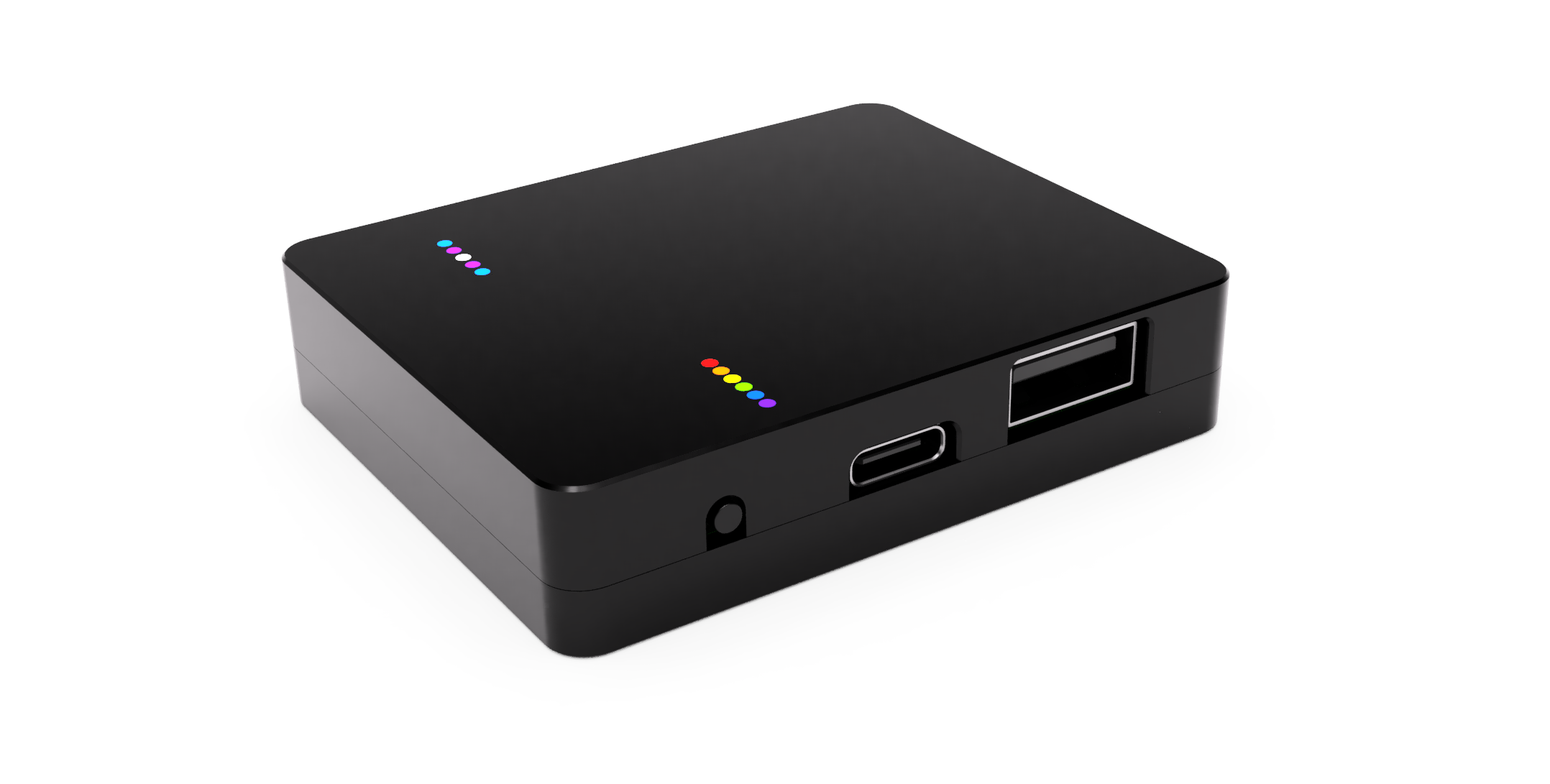
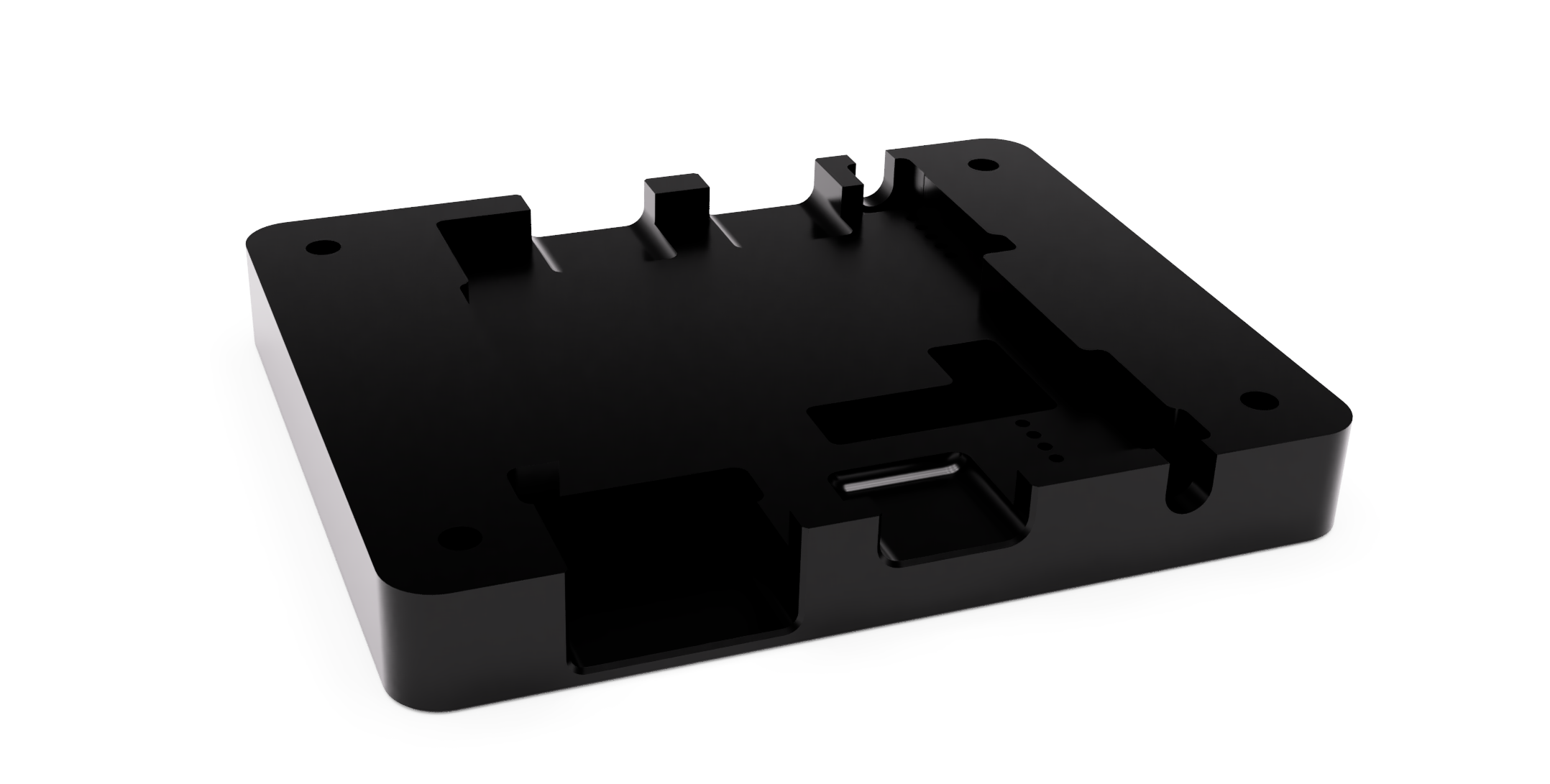
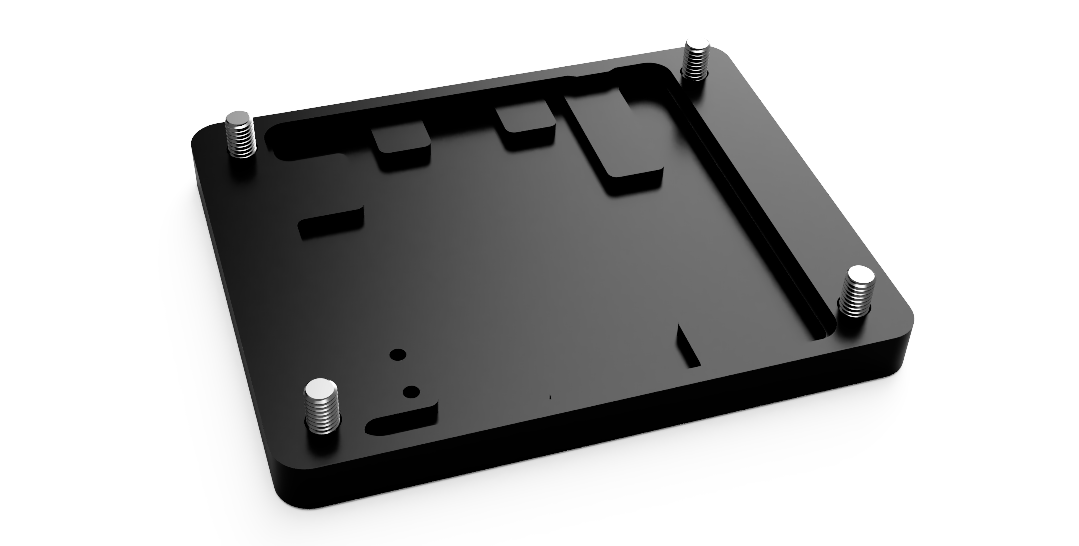
A little over two weeks ago we approached our manufacturers with the case design to get the first prototypes made. In the time since the campaign launched, we have received pictures of the freshly milled top pieces of the enclosure.
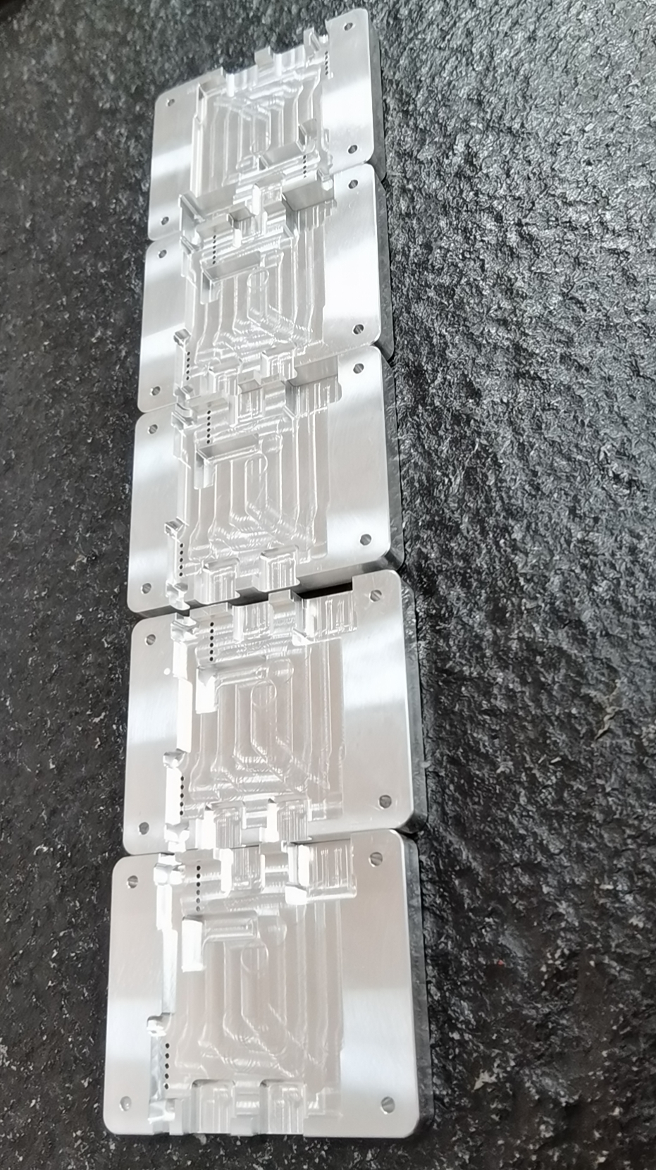
Once milling is finished, these prototypes will be sandblasted, anodized, and laser etched. Sandblasting will remove the tool marks from the interior of the cases, anodizing will coat the aluminum and turn it black, as shown in the 3D renders. Laser etching will add the labels, GSG markings, and other symbols to the case.
We really look forward to receiving these prototype cases soon, testing them, and uploading pictures/updates for you shortly after!
Announcing the LUNA Crowd Supply Campaign!
Today marks the day that our campaign to fund LUNA launches on Crowd Supply! Over the next six weeks (from July 15th to August 26th) anyone will be able to pre-purchase a LUNA and support our goal of bringing this low-cost multi-tool for building, analyzing, and hacking USB devices to market. If you want to learn more about LUNA, we have a detailed writeup of the device on our Crowd Supply campaign page that we hope you will read!
